


Special offers from our partners!

Find Replacement BBQ Parts for 20,308 Models. Repair your BBQ today.
111410-01C
For more information, visit www.desatech.com
For more information, visit www.desatech.com
11
11
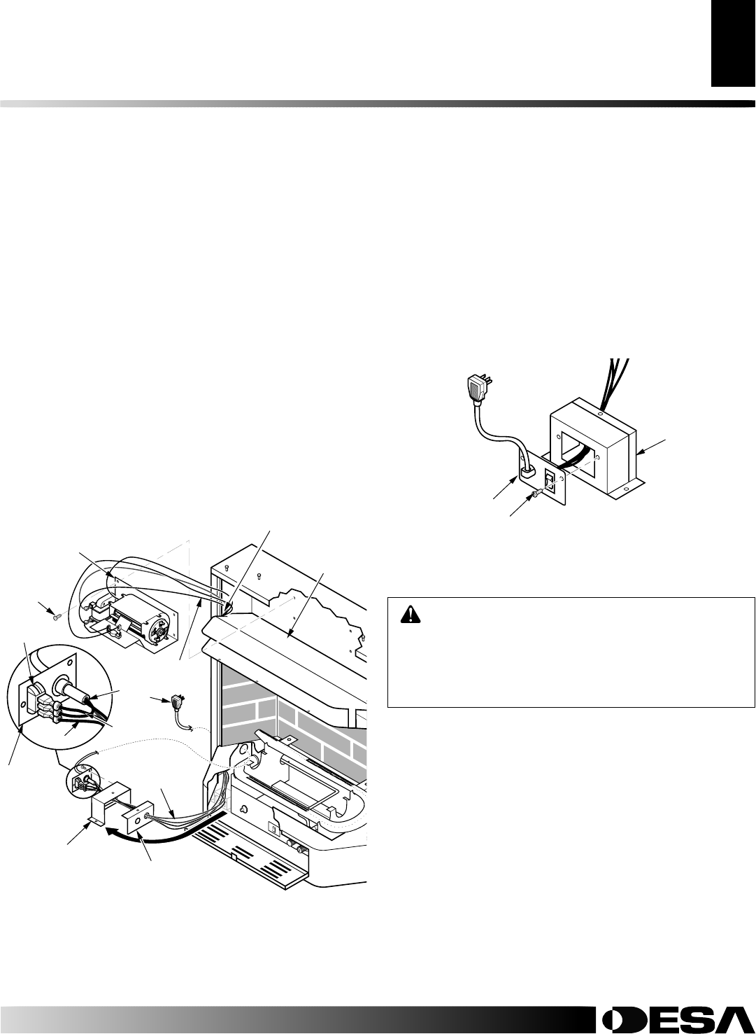
INSTALLATION
Continued
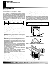
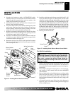
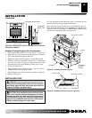
4. Note the wire locations on back of AUTO/OFF/ON switch.
Carefully remove red wire from the AUTO terminal and blue
wire from the ON terminal. Black wire can remain on the
middle or OFF terminal (see Figure 16).
5. Carefully disconnect green and white wires from power cord
harness at their insulated connectors.
6. In top of the heater cabinet, locate the four mounting holes on the
outer casing. Align these four holes with those on the blower
bracket assembly. Attach blower bracket assembly to the outer
casing with 4 - #10 screws provided (see Figure 16).
7. Route the wire harness through the hole to the left side of heat
deflector. Pull wire harness through lower opening to the left
of the blower control shield. (see Figure 16).
8. Insert the 4 wire harness into one of the round holes in the rear
of the blower control shield and through the rectangular hole
in the front of shield (see Figure 16).
9. Reconnect red wire to the AUTO switch position. Reconnect
blue wire to the ON switch position. Reconnect green and white
wires to the power cord.
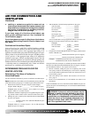
Figure 16 - Installing Blower Bracket Assembly
A
U
T
O
O
F
F
O
N
Wire Harness
Blower Bracket
Assembly
Screw
Power
Cord
Blower
Control
Shield
Shield Cover
Wire
Harness
Switch
Plate
Switch
Heat
Deflector
Wiring Routing Hole
Blue
Red
Blower
Control
Shield
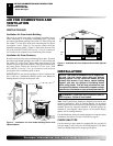
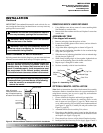
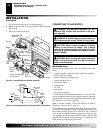
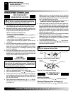
Figure 17 - Installing Switch Plate to Blower Control Shield
Switch Plate
Screw
INSTALLATION
Installing Blower Assembly - GA3450T (Cont.)
10. Install the switch plate on the blower control shield with 2 - #10
screws provided (see Figure 17). Route power cord out of the
cabinet by inserting it through the bushing on the outer casing
(see Figure 16). Plug fan kit into 120-Volt grounded power sup-
ply and test operation.
Note:
When switch is in the AUTO posi-
tion, the fan will start after the heater has run for a few mo-
ments. The fan will continue to run for several moments after
the heater has been turned off. When switch is in the ON posi-
tion, the fan will run until turned to OFF. Reinstall hood assem-
bly and close lower louver door.
11. Place log set back on the unit.
WARNING: A licensed electrician must connect
the wiring harness to electrical supply following all
local codes. Electrician must provide a clamp on the
box cover to secure the wiring. Wiring should be
routed through the bushing in the hole on the outer
casing of heater.
1. Install a snap bushing found in hardware kit into one of the
holes found on rear of blower control shield. The other hole is
for a strain relief clamp (not supplied) to secure incoming elec-
trical supply.
2. Follow steps 2 through 6 in Installing Blower Assembly begin-
ning on page 10. Also remove black wire from middle/OFF
switch terminal.
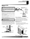
3. Remove black plastic strain relief and power cord from switch
plate (see Figure 18, page 12). The power cord supplied will
not be used in built-in installations. Pop in the plastic snap
bushing found in hardware kit into the hole left by supply cord/
strain relief.
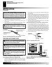
4. A licensed electrician must follow the wiring diagram in
Figure 19, page 12 to connect incoming electrical supply to
fan kit wiring harness.
For Built-In Installation