


Special offers from our partners!

Find Replacement BBQ Parts for 20,308 Models. Repair your BBQ today.
111410-01C
For more information, visit www.desatech.com
For more information, visit www.desatech.com
14
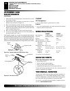
O
POSI
P
O
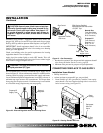
Open
Closed
Equipment
Shutoff Valve
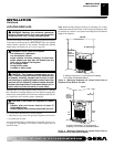
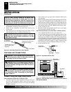
Figure 24 - Equipment Shutoff Valve
Pressure Testing Gas Supply Piping System
Test Pressures In Excess Of 1/2 PSIG (3.5 kPa)
1. Disconnect appliance with its appliance main gas valve (con-
trol valve) and equipment shutoff valve from gas supply
piping system. Pressures in excess of 1/2 psig will damage
fireplace regulator.
CHECKING GAS CONNECTIONS
WARNING: Test all gas piping and connections,
internal and external to unit, for leaks after installing
or servicing. Correct all leaks at once.
WARNING: Never use an open flame to check for
a leak. Apply a noncorrosive leak detection fluid to
all joints. Bubbles forming show a leak. Correct all
leaks at once.
CAUTION: Make sure external regulator has been
installed between propane/LP supply and fireplace.
See guidelines under
Connecting to Gas Supply
,
pages 12 and 13.
2. Cap off open end of gas pipe where equipment shutoff valve
was connected.
3. Pressurize supply piping system by either opening propane/LP sup-
ply tank valve for propane/LP gas or opening main gas valve lo-
cated on or near gas meter for natural gas, or using compressed air.
4. Check all joints of gas supply piping system. Apply noncorrosive
leak detection fluid to gas joints. Bubbles forming show a leak.
5. Correct all leaks at once.
6. Reconnect heater and equipment shutoff valve to gas supply.
Check reconnected fittings for leaks.
Test Pressures Equal To or Less Than 1/2 PSIG (3.5 kPa)
1. Close equipment shutoff valve (see Figure 24).
2. Pressurize supply piping system by either opening propane/LP sup-
ply tank valve for propane/LP gas or opening main gas valve lo-
cated on or near gas meter for natural gas, or using compressed air.
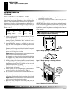
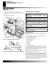
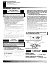
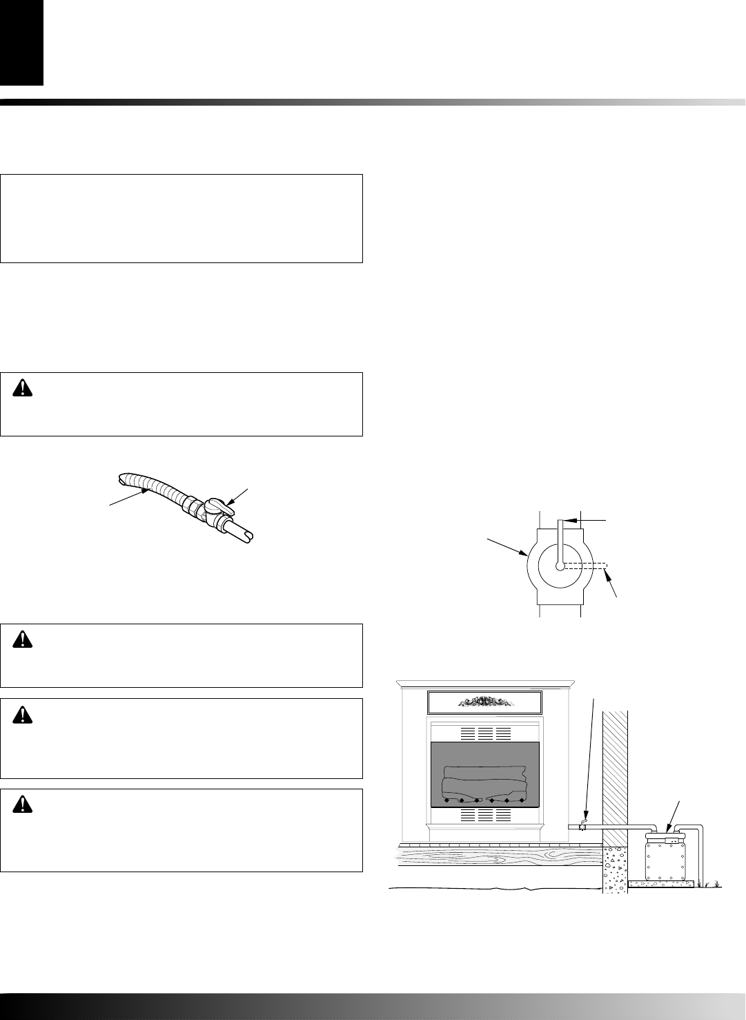
3. Check all joints from gas meter for natural gas (see Figure 25)
or propane/LP supply tank to equipment shutoff valve for pro-
pane/LP gas (see Figure 26, page 15). Apply noncorrosive leak
detection fluid to gas joints. Bubbles forming show a leak.
4. Correct all leaks at once.
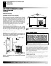
INSTALLATION
Continued
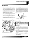
NOTICE: Most building codes do not permit con-
cealed gas connections. A flexible gas line is pro-
vided to allow accessibility from the fireplace (see
Figure 23). The flexible gas supply line connection to
the equipment shutoff valve should be accessible.
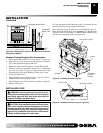
2. Apply pipe joint sealant lightly to male threads of gas connec-
tor attached to flexible gas line (see Figure 23).
3. Check all gas connections for leaks. See Checking Gas
Connections.
4. Feed flexible gas line into fireplace base area. Make sure the
entire flexible gas line is in fireplace mantel base area.
Figure 23 - Attaching Flexible Gas Lines Together
CAUTION: Avoid damage to regulator. Hold gas
regulator with wrench when connecting it to gas
piping and/or fittings.
Flexible Gas Line
from Fireplace Gas
Regulator
To Fireplace
Gas Regulator
Equipment Shutoff Valve
Provided by Installer
To Gas Meter
➞
➞
Gas Meter
Figure 25 - Checking Gas Joints for Natural Gas Unit (Shown
With Optional Mantel)
Equipment
Shutoff Valve
INSTALLATION
Connecting Fireplace to Gas Supply (Cont.)
Checking Gas Connections