


Special offers from our partners!

Find Replacement BBQ Parts for 20,308 Models. Repair your BBQ today.
111410-01C
For more information, visit www.desatech.com
For more information, visit www.desatech.com
13
13
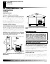
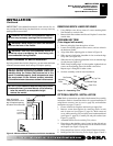
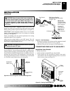
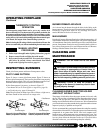
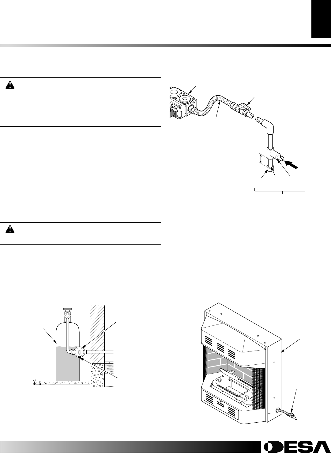
Figure 20 - External Regulator with Vent Pointing Down
CAUTION: Use only new, black iron or steel pipe.
Internally-tinned copper tubing may be used in cer-
tain areas. Check your local codes. Use pipe of 1/2"
or greater diameter to allow proper gas volume to
fireplace. If pipe is too small, undue loss of volume
will occur.
WARNING: Use pipe joint sealant that is resistant
to liquid petroleum (LP) gas.
Installation must include a equipment shutoff valve, union, and
plugged 1/8" NPT tap. Locate NPT tap within reach for test gauge
hook up. NPT tap must be upstream from fireplace (see Figure 21).
IMPORTANT:
Install equipment shutoff valve in an accessible
location. The equipment shutoff valve is for turning on or shutting
off the gas to the appliance.
Check your building codes for special requirements for locating
equipment shutoff valve to fireplaces.
Apply pipe joint sealant lightly to male NPT threads. This will
prevent excess sealant from going into pipe. Excess sealant in pipe
could result in clogged fireplace valves.
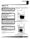
We recommend that you install a sediment trap in supply line as
shown in Figure 21. Locate sediment trap where it is within reach for
cleaning. Install in piping system between fuel supply and heater.
Locate sediment trap where trapped matter is not likely to freeze. A
sediment trap traps moisture and contaminants. This keeps them
from going into fireplace controls. If sediment trap is not installed
or is installed wrong, fireplace may not run properly.
Propane/LP
Supply Tank
Vent Pointing
Down
External
Regulator
INSTALLATION
Continued
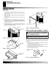
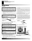
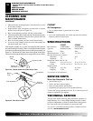
Cap Pipe Tee
Nipple Joint
3" Minimum
Sediment Trap
Gas Control
Natural Gas
From Gas Meter
(5" W.C.** to 10.5
W.C. Pressure)
Propane/LP
From External
Regulator (11"
W.C.** to 14"
W.C. Pressure)
CSA Design-Certified
Equipment Shutoff Valve With
1/8" NPT Tap*
Approved Flexible
Gas Hose
* Purchase the optional CSA design-certified equipment shutoff
valve from your dealer. See Accessories, page 29.
** Minimum inlet pressure for purpose of input adjustment.
Figure 21 - Gas Connection
A
U
T
O
O
F
F
O
N
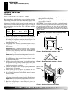
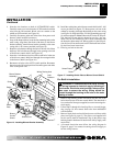
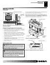
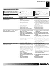
Figure 22 - Routing Flexible Gas Line
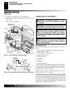
CONNECTING FIREPLACE TO GAS SUPPLY
Installation Items Needed
• Phillips screwdriver
• sealant (resistant to propane/LP gas, not provided)
1. Route flexible gas line (provided by installer) from equip-
ment shutoff valve into fireplace through side or rear access
holes in outer casing (see Figure 22).
Equipment
Shut Off
Valve
Outer
Casing
To Gas
Supply
INSTALLATION
Connecting to Gas Supply (Cont.)
Connecting Fireplace to Gas Supply