


Special offers from our partners!

Find Replacement BBQ Parts for 20,308 Models. Repair your BBQ today.
111410-01C
For more information, visit www.desatech.com
For more information, visit www.desatech.com
18
CABINET
Air Passageways
• Use a vacuum cleaner or pressurized air to clean.
Exterior
• Use a soft cloth dampened with a mild soap and water mixture.
Wipe the cabinet to remove dust.
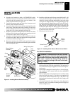
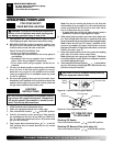
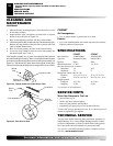
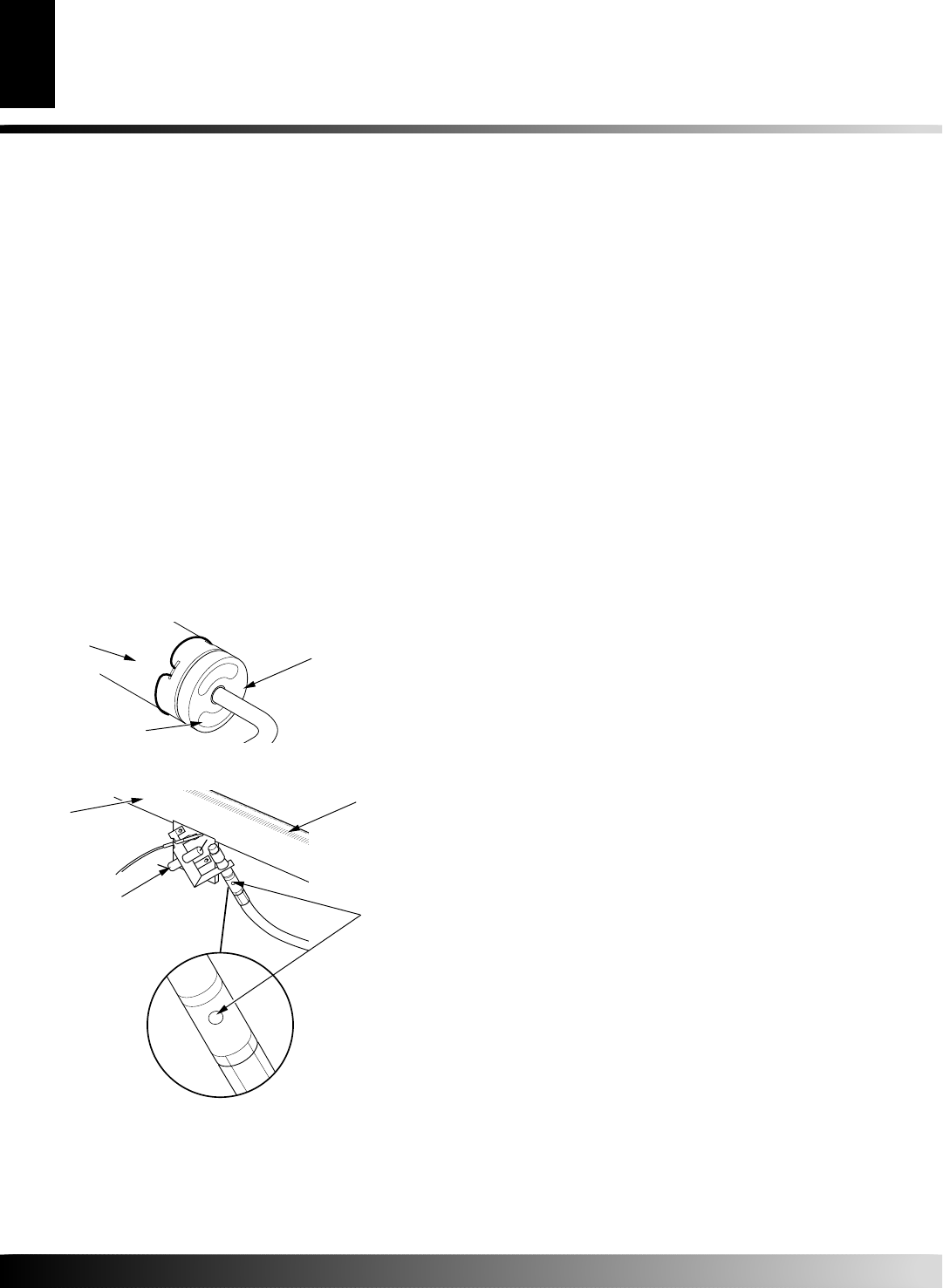
Figure 33 - Injector Holder On Outlet Burner Tube
Burner
Tube
Injector Holder
Primary Air
Inlet Holes
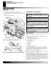
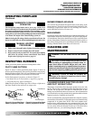
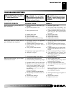
Figure 34 - Pilot Inlet Air Hole
Burner
Tube
Pilot Assembly
Pilot Air
Inlet Hole
Ports/Slots
SPECIFICATIONS
CF26PT CF26NT
Btu (Variable) 19,000/26,000 19,000/26,000
Type Gas Propane/LP Only Natural Only
Ignition Piezo Piezo
Manifold Pressure 8" W.C. 3.5" W.C.
Inlet Gas Pressure (in. of water) *
Maximum 14" 10.5"
Minimum 11" 5"
Dimensions, Inches (H x W x D)
Fireplace 25
7
/8 x 27 x 13
3
/4 25
7
/8 x 27 x 13
3
/4
Carton 28 x 26
13
/16 x 16
1
/2 28 x 26
13
/16 x 16
1
/2
Weight, pounds
Fireplace 44
1
/2 lbs. 44
1
/2 lbs.
Shipping 55 lbs. 55 lbs.
* For purposes of input adjustment
TECHNICAL SERVICE
You may have further questions about installation, operation, or
troubleshooting. If so, contact DESA Heating Products’ Techni-
cal Service Department at 1-866-672-6040. When calling, please
have your model and serial numbers of your heater ready.
You can also visit DESA Heating Products’ technical services
web site at www.desatech.com.
When Gas Pressure Is Too Low
• pilot will not stay lit
• burners will have delayed ignition
• heater will not produce specified heat
• propane/LP gas supply may be low (propane/LP only)
You may feel your gas pressure is too low. If so, contact your local
natural or propane/LP gas supplier.
SERVICE HINTS
1. Shut off the unit, including the pilot. Allow the unit to cool for
at least thirty minutes.
2. Inspect burners, pilot, and primary air inlet holes on injector
holder for dust and dirt (see Figure 33).
3. Blow air through the ports/slots and holes in the burners.
4. Check the injector holder located at the end of the burner tube again.
Remove any large particles of dust, dirt, lint, or pet hair with a soft
cloth or vacuum cleaner nozzle.
5. Blow air into the primary air holes on the injector holder.
6. In case any large clumps of dust have now been pushed into
the burner repeat steps 3 and 4.
Clean the pilot assembly also. A yellow tip on the pilot flame indicates
dust and dirt in the pilot assembly. There is a small pilot air inlet hole about
two inches from where the pilot flame comes out of the pilot assembly (see
Figure 34). With the unit off, lightly blow air through the air inlet hole.
You may blow through a drinking straw if compressed air is not available.
CLEANING AND
MAINTENANCE
continued
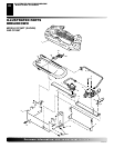
CLEANING AND MAINTENANCE
Cleaning Burner Injector Holder and Pilot Air Inlet Hole (Cont.)
Cabinet
SPECIFICATIONS
SERVICE HINTS
TECHNICAL SERVICE