


Special offers from our partners!

Find Replacement BBQ Parts for 20,308 Models. Repair your BBQ today.

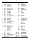
Page 4 R-3848
IMPORTANT INFORMATION ABOUT YOUR NEW TYPE-1
GRILL CONNECTION
Read all grill and related product literature before connecting or using
your grill, and please read the following information completely before
attempting to connect your grill to a propane cylinder.
Keep these instructions in a safe place. You may need to refer to them
when connecting other cylinders after filling.
Your new grill regulator is equipped with a coupling nut . Do not attempt
to connect any propane cylinder not equipped with a mating Type-1
cylinder valve.
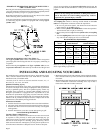
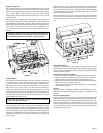
Figure 1
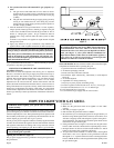
Connecting the Regulator to the Valve (Figure 1)
This Type-1 cylinder valve contains a backcheck which is designed to
prevent propane from flowing until the valve is properly connecting to
a regulator.
When connecting the regulator to the Type-1 cylinder valve, be sure
the pressure relief valve is directed away from the front of the grill and
away from any building. If the pressure relief valve should open, the
propane will then be directed where it is likely to do the least harm if
ignited.
WARNING: Do not insert any foreign objects into the valve
outlet. You may damage the backcheck. A damaged backcheck
can be the source of a leak. Leaking propane may result in
explosion, fire, personal injury or death.
Regulator Coupling Nut
The coupling nut connects to the large outside threads on the valve
outlet. To complete the connection, follow the steps below.
1. Be sure all grill burner knobs, side burner knob and rotisserie
burner knob are in the OFF position.
2. Make sure the cylinder valve handwheel is in the closed position.
Turn clockwise (left to right) to a full stop.
3. Remove the protective caps from the cylinder valve and coupling
nut.
4. Turn the coupling nut clockwise (left to right), to tighten to a full
stop. Be sure the coupling nut is not cross-threaded.
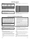
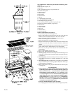
Recommended Gas Pipe Diameter
Pipe Length Schedule 40 Pipe Tubing, Type L
(Feet) Inside Diameter Outside Diameter
Nat. L.P. Nat. L.P.
0-10 1/2" 3/8" 1/2" 3/8"
1.3 cm 1.0 cm 1.3 cm 1.0 cm
10-40 1/2" 1/2" 5/8" 1/2"
1.3 cm 1.3 cm 1.6 cm 1.3 cm
40-100 1/2" 1/2" 3/4" 1/2"
1.3 cm 1.3 cm 1.9 cm 1.3 cm
100-150 3/4" 1/2" 7/8" 3/4"
1.9 cm 1.3 cm 2.2 cm 1.9 cm
Note: Never use plastic pipe. Check to confirm whether your local codes
allow copper tubing or galvanized.
INSTALLING AND LOCATING YOUR GRILL
The installation must conform with local codes or, in the absence of local
codes, with the National Fuel Gas Code ANSI Z223.1*/ Canadian
Installation Code, CAN/CGA-B149.
*Available from the American National Standards Institute, Inc., 11
West 42nd St., New York, NY 10036.
Qualified Installing Agency
Installation and replacement of gas piping, gas utilization equipment or
accessories and repair and servicing of equipment shall be performed
only by a qualified agency. The term "qualified agency" means any
individual, firm, corporation or company which whether in person or
through a representative is engaged in and is responsible for (a) the
installation or replacement of gas piping or (b) the connection, installa-
tion, repair or servicing of equipment, who is experienced in such work,
familiar with all precautions required and has complied with all the
requirements of the authority having jurisdiction.
Instruction to Installer
1. Installer must leave instruction manual with owner after installation.
2. The owner shall retain this instruction manual for future reference.
3. Installer must have owner fill out and mail warranty card supplied
with appliance.
4. Installer should show owner how to start and operate gas grill.
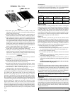
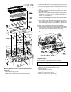
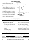
LOCATION REQUIREMENTS
Location (Figure 2 and Figure 3)
When determining a suitable location take into account concerns such
as exposure to wind, proximity to traffic paths and keeping any gas
supply lines as short as possible. Locate the grill only in well ventilated
area. Never locate the grill in a building, garage, breezeway, shed or
other such enclosed areas. During heavy use the grill will produce a lot
of smoke. Ensure that there is adequate area for smoke to dissipate.
• Minimum clearance from sides and back of unit to adjacent combus-
tible construction below top of unit, 6 inches from sides and 12 inches
from back.
• Minimum horizontal clearance from sides and back of unit to adjacent
vertical combustible construction extending above top of unit, 6
inches from sides and 12 inches from back.
Figure 2