


Special offers from our partners!

Find Replacement BBQ Parts for 20,308 Models. Repair your BBQ today.

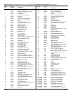
R-3848 Page 11
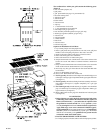
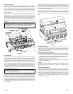
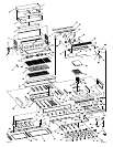
Figure 11
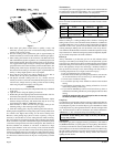
Removing Rotisserie Burners and Rotisserie Burner Orifices
(Figure 12)
1. Turn OFF gas supply to grill.
2. All grill parts must be cool before attempting to clean.
3. Remove (1) screw from each rotisserie burner electrode.
4. Pull forward on the electrode to expose approximately 3 inches of the
electrode wire.
5. If you are replacing the electrode, remove the electrode wire from the
electrode. Do not allow the electrode wire to slip back into the access
hole.
6. If you are not replacing the electrode, allow the electrode to lay on
the cooking surface.
7. Remove (6) screws from the brackets for the elevated cooking racks.
The brackets are located at each end (2 brackets) and between (1
bracket) the rotisserie burners.
8. At the center of the gas grill, grasp the end of rotisserie burner, pull
forward and slide the opposite end of the rotisserie burner from the
orifice fitting.
9. Apply air pressure into the face and end of the rotisserie burner to
remove spiders, spider webs, dust, lint and debris. A flexible, soft
bristle, bottle brush can be used to clean the interior of the rotisserie
burner.
10. Remove the rotisserie burner orifice from the orifice fitting.
11. Apply air pressure into the rotisserie burner orifice and orifice fitting
to remove spiders, spider webs, dust, lint and debris. A flexible, soft
bristle, bottle brush can be used to clean the orifice fitting.
12. To reinstall components, reverse above procedure starting with Step
10.
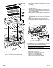
Figure 12
Cleaning the Orifices
No regular maintenance should be needed for the orifices. They should
only be removed if it is determined that there is a blockage.
Warning: Serious injury may occur if the orifice is not located
properly in the orifice fitting when reassembled.
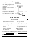
Removing and Replacing the Piezo Ignitors and Electrodes
1. Remove all gas control knobs and ignitor knobs.
2. Remove chip tray.
3. Remove valve cover (7 screws).
4. Piezo ignitors are located at rear of valve cover.
5. Remove (1) screw for each electrode.
6. Remove (2) screws for each piezo ignitor.
7. Reverse above procedure to replace components.