


Special offers from our partners!

Find Replacement BBQ Parts for 20,308 Models. Repair your BBQ today.
Buy Weber Grill Parts. It couldn't be easier. Find your Weber parts here.
30 WWW.WEBER.COM
®
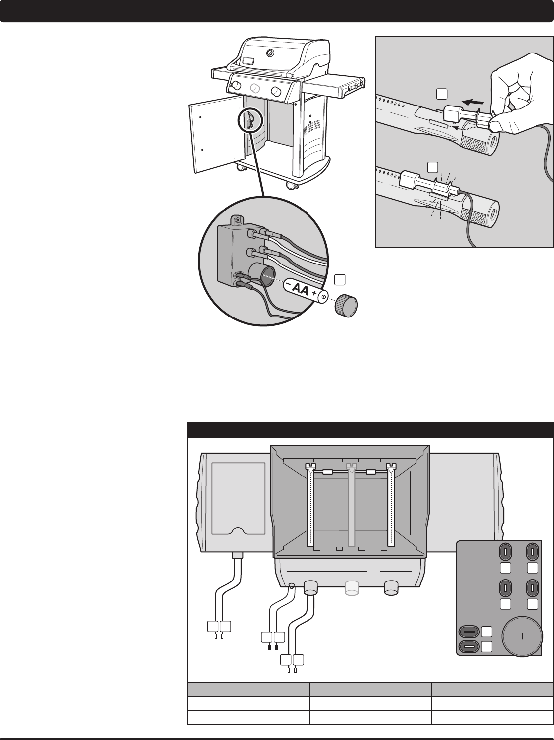
ROUTINE MAINTENANCE
MAINTAINING THE ELECTRONIC
CROSSOVER
®
IGNITION SYSTEM
The igniter module supplies power to the electronic
Crossover
®
ignition system and the side burner with
one igniter button. Whether you are performing routine
maintenance or a troubleshooting check on the ignition
system, read the following to keep your ignition system
working properly.
If the electronic Crossover
®
ignition system fails to ignite,
you'll need to pinpoint where the problem is occurring:
with the gas ow or with the electronic ignition system.
Begin by attempting to match light your burners. Refer
to“MAINBURNERIGNITION-LightingwithaMatch.”
If match lighting is successful, the problem lies in the
ignition system.
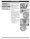
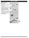
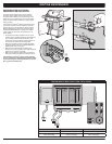
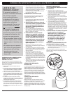
• VerifythattheAAbattery(alkalineonly)isingood
condition and is installed correctly (1). Some batteries
have a plastic protective wrap around them. This
plastic must be removed before installing battery. Do
not confuse this plastic with the battery label.
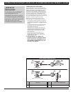
• Makesuretheigniterwiresareproperlyattachedto
theignitermodule.Refertothe“IGNITERMODULE
WIREGUIDE”chartonthispage.
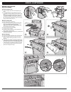
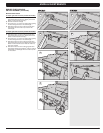
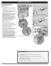
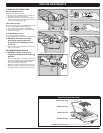
• Makesuretheceramicigniterassemblyisfully
inserted into burner tube igniter channel (2). If properly
positioned, you will hear a snap (3).
• Makesuretheelectronicigniterbuttonisworkingby
listening for clicking and looking for sparks at burner.
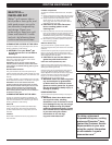
If the electronic Crossover
®
ignition system still fails
to ignite, contact the Customer Service Representative
in your area using the contact information on our web
site. Log onto www.weber.com
®
.
1
2
3
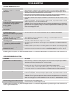
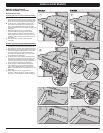
IGNITER MODULE WIRE CHART (E220 / E320 / SP320)
1
2
1
2
5
6
3
4
3
4
5
6
BURNER 1 SIDE BURNER IGNITER BUTTON
Black Terminal (1) Blue Terminal (3) Black Terminal (5)
Yellow Terminal (2) Green Terminal (4) Black Terminal (6)