


Special offers from our partners!

Find Replacement BBQ Parts for 20,308 Models. Repair your BBQ today.
7
106516
OWNER’S MANUAL
WARNING: Read all instruc-
tions completely and thoroughly
before attempting installation.
Failure to do so could result in
serious injury, property damage
or loss of life. Operation of im-
properly installed and maintained
venting system could result in
serious injury, property damage
or loss of life.
WARNING: Seal all vent con-
nections. Seal only the outer pipe
connections with high temperature
silicone (600°F/316° C). Before join-
ing elbows and pipes, apply a bead
of high temperature silicone seal-
ant (GE RTV 106/Loctite RTV 81585)
to the male end of the elbow or
pipe. High temperature silicone
must also be used to re-seal any
connections after maintenance to
venting system.
NOTICE: Failure to follow these
instructions will void the warranty.
INSTALLATION
PRECAUTIONS
Consult local building codes before beginning
the installation. The installer must make sure
to select the proper vent system for installa-
tion. Before installing vent kit, the installer
must read this fireplace manual and vent kit
instructions.
Only a qualified service person should in-
stall venting system. The installer must fol-
low these safety rules:
• Wear gloves and safety glasses for
protection
• Use extreme caution when using ladders
or when on roof tops
• Be aware of electrical wiring locations
in walls and ceilings
The following actions will void the war-
ranty on your venting system:
• Installation of any damaged venting
component
• Unauthorized modification of the vent-
ing system
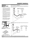
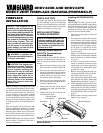
VENTING
INSTALLATION
WARNING: This gas fireplace
and vent assembly must be
vented directly to the outside.
The venting system must NEVER
be attached to a chimney serving
a separate solid fuel burning ap-
pliance. Each gas appliance must
use a separate vent system. Do
not use common vent systems.
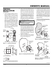
WARNING: Horizontal sec-
tions of this vent system require a
minimum clearance of 2" from the
top of the pipe and 1" minimum to
the sides and bottom. 1
1
/2" clear-
ance is required where the termi-
nation penetrates a combustible
wall. Vertical sections of this sys-
tem require a minimum of 1" clear-
ance to combustible materials on
all sides of the pipe.
• Installation of any component part not
manufactured or approved by DESA
International
• Installation other than as instructed by
these instructions
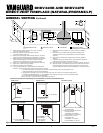
INSTALLATION PLANNING
There are two basic types of direct-vent
installation:
• Horizontal Termination
• Vertical Termination
It is important to select the proper length of
vent pipe for the type of termination you
choose. It is also important to note the wall
thickness.
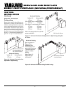
For Horizontal Termination: Select the
amount of vertical rise desired. The horizon-
tal run of venting must have 1/4" rise for
every 12" of run towards the termination.
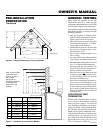
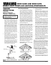
NOTICE: Treatment of firestops
and construction of the chase may
vary from building type to build-
ing type. These instructions are
not substitutes for the require-
ments of local building codes. You
must follow all local building
codes.
Note:
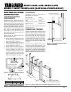
When installing in a chase, you should
insulate the chase as you would the outside
walls of your home. This is especially im-
portant in cold climates. Minimum clear-
ance between vent pipes and combustible
materials such as insulation is 1".
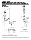
After framing the chase (see Framing and
Finishing on pages 4 and 5) install the vent
system by following the installation in-
structions.
Installing Vent System in a Chase
A chase is a vertical boxlike structure built
to enclose venting that runs along the out-
side of a building. A chase is not required for
such venting.
Continued
WARNING: Never run the vent
downward as this may cause ex-
cessive temperatures which
could cause a fire.
You may use one or two 90° elbows in this
vent configuration. See Horizontal Termina-
tion Configurations on pages 10 and 11.
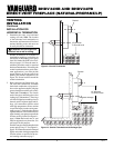
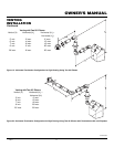
For Vertical Termination: Measure the dis-
tance from the fireplace flue outlet to the
ceiling. Add the ceiling thickness, the verti-
cal rise in an attic or second story, and allow
for sufficient vent height above the roofline.
You may use one or two 90° elbows in this
vent configuration. See Vertical Termination
Configurations on pages 13 and 14.
Note:
You may use two 45° elbows in place
of a 90° elbow. You must follow rise to run
ratios when using 45° elbows.
For two-story applications, firestops are re-
quired at each floor level. If an offset is
needed in the attic, additional pipe and el-
bows will be required.
You may use a chase with a vent termination
with exposed pipe on the exterior of the house.
See Installing Vent System in a Chase, below.
Your Vanguard direct-vent fireplace has been
tested for a minimum 3' rise with a maximum
10" wall thickness. The maximum horizon-
tal run is 20' with 8' vertical rise (see Instal-
lation for Horizontal Termination, page 8).
The maximum vertical run is 30' (see Instal-
lation for Vertical Termination, page 12).
It is very important that the venting system
maintain its balance between the combus-
tion air intake and the flue gas exhaust.
Certain limitations apply to vent configura-
tions and must be strictly followed.