


Special offers from our partners!

Find Replacement BBQ Parts for 20,308 Models. Repair your BBQ today.
27
106516
OWNER’S MANUAL
INSPECTING
BURNERS
Check pilot flame pattern and burner flame
patterns often.
PILOT ASSEMBLY
The pilot assembly is factory preset for the
proper flame height. Alterations may have
occurred during shipping and handling. Call
a qualified service person to readjust the
pilot if necessary.
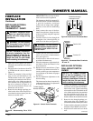
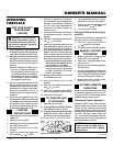
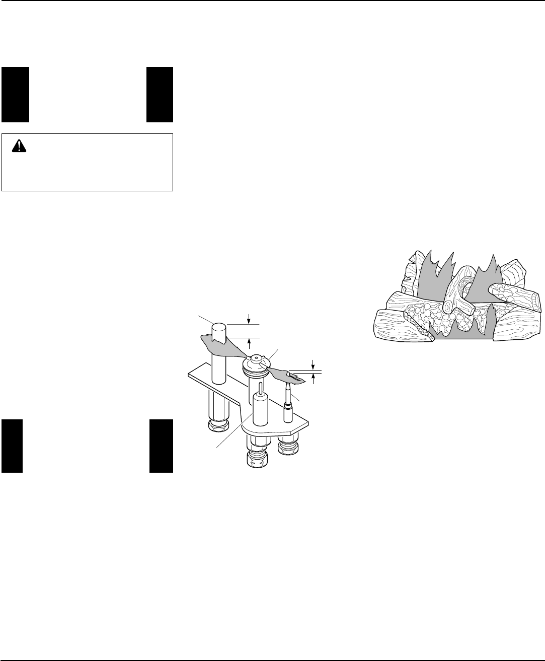
The height of the thermopile must be 3/8" to
1/2" above the pilot flame as shown in Figure
59. The thermocouple must be at a height of
about 1/8" above the pilot flame. The flame
from the pilot burner must extend beyond
both the thermocouple and thermopile.
If your pilot assembly does not meet these
requirements:
• turn fireplace off (see To Turn Off Gas to
Appliance, page 25)
• see Troubleshooting, pages 29 through 31
BURNER FLAME PATTERN
Burner flames will be steady; not lifting or
floating. Flame patterns will be different
from unit to unit and will vary depending on
installation type and weather conditions.
If the vent configuration is installed incor-
rectly, the flames will lift or "ghost". This
can be dangerous. Inspect the flames after
installation to ensure proper installation and
performance.
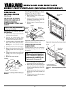
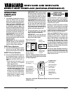
Figure 60 shows a typical flame pattern for
BHDV34NB and BHDV34PB.
If burner flame pattern differs from that
described:
• turn fireplace off (see To Turn Off Gas to
Appliance, page 25)
• see Troubleshooting, pages 29 through 31
Figure 59 - Pilot Assembly
Figure 60 - Typical Flame Pattern for
models BHDV34NB and BHDV34PB
Thermocouple
Thermopile
3/8" to 1/2"
1/8"
Pilot Burner
Piezo
Ignitor
OPERATING
FIREPLACE
Continued
OPERATING
OPTIONAL GWMT1
WALL MOUNTED
THERMOSTAT
Light the fireplace as instructed in Light-
ing Instructions on page 25. Set wall ther-
mostat to desired temperature.
This thermostat has been electronically
calibrated at the factory and requires no
adjustment or leveling.
Upon installation, the thermostat must
be allowed to stabilize at room tempera-
ture for a minimum of 30 minutes for
proper operation.
To turn the fireplace off, adjust thermo-
stat to the lowest setting and turn the gas
control knob back to PILOT. The pilot
will remain lit.
IMPORTANT:
To turn the pilot off, turn
the gas control knob on the heater to the
OFF position.
WARNING: Do not connect
the thermostat to a power source.
Electrical shock and/or a fire haz-
ard will occur.
OPERATING
OPTIONAL GWMS2
WALL MOUNTED
SWITCH
Make sure the heater switch is on AUTO.
This wall switch works just like the con-
ventional light switch. Flip the switch up
for on and down for off.
Note:
Make sure that this switch is not in
a position to be mistaken for a light switch.
This may result in the heater being inad-
vertently turned on without the proper
precautions being taken. See installation
instructions on page 21 of this manual.