


Special offers from our partners!

Find Replacement BBQ Parts for 20,308 Models. Repair your BBQ today.

10
106516
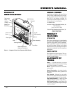
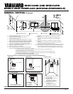
DIRECT-VENT FIREPLACE (NATURAL/PROPANE/LP)
®
BHDV34NB AND BHDV34PB
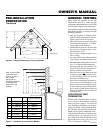
VENTING
INSTALLATION
Continued
UP
UP
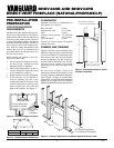
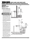
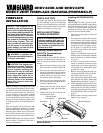
Horizontal Venting
Vertical (V) Horizontal (H)
37" min. 10" max.
Figure 16 - Horizontal Termination Con-
figuration for Rigid Venting
Figure 17 - Horizontal Termination Configuration for Rigid Venting Using One
90
°
Elbow
Figure 18 - Horizontal Termination Using Flexible Venting
Horizontal Venting
Vertical (V) Horizontal (H)
44" min. 29" max.
(30° and 90° only, no vertical pipe)
55" min. 41" max.
(30° elbow, 1' vertical pipe, 90° elbow)
67" min. 60" max.
79" min. 84" max.
96" min. 20' max.
Note:
This configuration for use with
corner installation.
UP
Horizontal Venting
See information in
Figure 17 for
Vertical(V) and
Horizontal(H) maxi-
mums and minimums.
The same amounts
apply for flexible
venting.
Note:
Figure 16
applies to rigid
venting only.
BGFVK Vent Kit Shown
(recommended for use
with cabinet mantels)
BVK Vent Kit Shown
BFGFVK and FGFVK
Vent Kits Shown
Horizontal Termination
Configurations
Figures 16 through 20 show different con-
figurations for venting with horizontal ter-
mination. Each figure includes a chart with
vertical minimum/maximum and horizon-
tal maximum dimensions which must be
met. Seal all connections with high tem-
perature silicone sealant (outer pipe only) as
specified in the second warning statement
on page 7. All horizontal terminations re-
quire 1/4" rise per 12" of horizontal run.