


Special offers from our partners!

Find Replacement BBQ Parts for 20,308 Models. Repair your BBQ today.

110150-01B
For more information, visit www.desatech.com
For more information, visit www.desatech.com
18
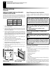
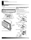
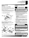
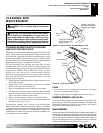
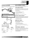
Locate the blower switch by opening lower louver on fireplace
insert. Blower switch is located at lower left inside louver door.
This thermostat-controlled blower has a variable speed control
that operates the blower. The blower will start when the ther-
mostat senses a sufficient increase in firebox temperature.
Note:
Your gas logs and thermostat blower will not turn on and
off at the same time. The fireplace insert may run for several
minutes before the blower turns on. After the heater modulates
to the pilot position, the blower will continue to run. The blower
will shut off after the firebox temperature decreases.
Note:
It is safe to operate fireplace insert with blower turned
off. However, the blower helps distribute heated air from the
fireplace insert.
OPTIONAL BLOWER
OPERATION
OPERATING FIREPLACE
INSERT
Continued
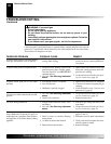
INSPECTING BURNERS
Check pilot flame pattern and burner flame patterns often.
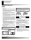
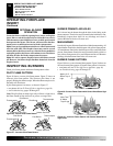
PILOT FLAME PATTERN
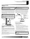
Figure 36 shows a correct pilot flame pattern. Figure 37 shows an
incorrect pilot flame pattern. The incorrect pilot flame is not
properly heating the thermocouple. When the thermocouple cools,
the heater will shut down.
If pilot flame pattern is incorrect, as shown in Figure 37
• turn heater off (see To Turn Off Gas to Appliance, page 16)
• see Troubleshooting, pages 20 through 22
Note:
The pilot flame on natural gas units will have a slight curve,
but flame should be blue and have no yellow or orange color.
BURNER PRIMARY AIR HOLES
Air is drawn into the burner through the holes in the fitting at the
burner entrance. These holes may become blocked with dust or lint.
Periodically inspect these holes for any blockage and clean if
needed. Blocked air holes will create soot.
MAIN BURNER
Periodically inspect all burner flame holes with the heater running. All
slotted burner flame holes should be open with yellow flame present.
All round burner flame holes should be open with a small blue flame
present. Some burner flame holes may become blocked by debris or
rust, with no flame present. If so, turn off heater and let cool. Remove
blockage, blocked burner flame holes will create soot.
BURNER FLAME PATTERN
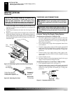
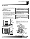
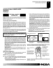
Figure 38 shows a correct burner flame pattern. Figure 39 shows an
incorrect burner flame pattern. If burner flame pattern is incorrect,
• turn heater off (see To Turn Off Gas to Appliance, page 16)
• see Troubleshooting, pages 20 through 22
Figure 38 - Correct Flame Pattern with Control Knob Set to High
Flame.
Figure 39 - Incorrect Flame Pattern with Control Knob Set to
High Flame
Approx. 3-6"
Above Top of
Logs
More Than
8" Above
Top of Logs
OPERATING FIREPLACE INSERT
Optional Blower Operation
INSPECTING BURNERS
Pilot Flame Pattern
Burner Primary Air Holes
Main Burner
Burner Flame Pattern
Figure 36 - Correct Pilot Flame Pattern
Figure 37 - Incorrect Pilot Flame Pattern
Pilot Burner
Thermocouple
Thermocouple
Pilot Burner
Thermocouple
Pilot Burner
Thermocouple
Pilot Burner
Natural Gas PilotPropane/LP Gas Pilot
Natural Gas PilotPropane/LP Gas Pilot