


Special offers from our partners!

Find Replacement BBQ Parts for 20,308 Models. Repair your BBQ today.
110150-01B
For more information, visit www.desatech.com
For more information, visit www.desatech.com
10
INSTALLATION
Continued
INSTALLATION
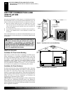
Fireplace Insert Installation Into Framed-In Enclosure
Installing Gas Piping To Fireplace Location
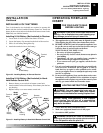
FIREPLACE INSERT INSTALLATION INTO
FRAMED-IN ENCLOSURE
Installation of this fireplace insert involves installing fireplace insert
into a framed-in enclosure. If using a mantel above the fireplace, you
must follow the clearances shown in Figure 14, page 9. Follow these
instructions to install the fireplace insert in this manner.
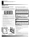
Insert Framing
Height 25
9
/
16
" 26
1
/
4
"
Front Width 34
5
/
16
" 35"
Depth 16
11
/
16
" 17
1
/
4
"
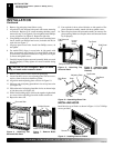
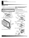
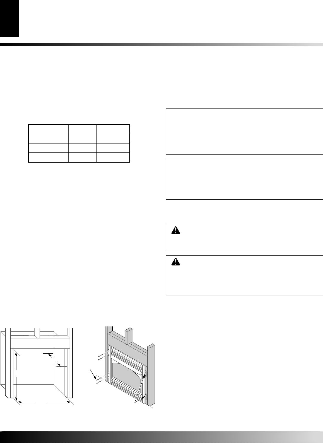
1. Frame in rough opening. Use dimensions shown in Figure 15
for the rough opening.
2. Install and properly ground GA3555, three-prong 120 volt elec-
trical outlet, in fireplace insert. Follow instructions included in kit
(see Accessories, page 30).
3. Install gas piping into fireplace location. This installation in-
cludes an approved flexible gas line (if allowed by local codes)
after the equipment shutoff valve. The flexible gas line must
be the last item installed on the gas piping. See Installing Gas
Piping to Fireplace Location.
4. Carefully set fireplace insert in front of rough opening with
back of insert inside wall opening.
5. Carefully set fireplace insert into rough opening.
6. Attach flexible gas line to gas supply. See Connecting Fire-
place Insert to Gas Supply, page 11.
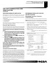
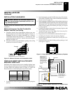
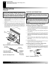
7. Attach fireplace to wall studs using nails or wood screws
through holes in nailing flange (see Figure 16).
8. Check all gas connections for leaks. See Checking Gas Con-
nections, page 12.
9. Install surround kit. See Installing Surround Kit (GS38 or
GS43), pages 7 and 8.
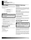
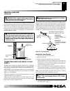
35"
17
1
/
4
"
26
1
/
4
"
Figure 15 - Rough Opening for
Installing in Wall
Figure 16 - Attaching Fireplace
Insert to Wall Studs
Nails or
Wood
Screws
Nailing Flanges
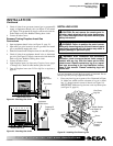
INSTALLING GAS PIPING TO FIREPLACE
LOCATION
Installation Items Needed
Before installing fireplace insert, make sure you have the items
listed below.
• external regulator (supplied by installer) (propane/LP units only)
• piping (check local codes)
• sealant (resistant to propane/LP gas)
• equipment shutoff valve *
• test gauge connection *
• sediment trap
• tee joint
• pipe wrench
• approved flexible gas line with gas connector (if allowed by lo-
cal codes) (not provided)
* A CSA design-certified equipment shutoff valve with 1/8" NPT
tap is an acceptable alternative to test gauge connection. Purchase
the optional CSA design-certified equipment shutoff valve from
your dealer. See Accessories, page 30.
WARNING: A qualified service person must con-
nect fireplace Insert to gas supply. Follow all local
codes.
NOTICE: If your installation does not meet the mini-
mum clearances shown, you must do one of the
following:
• raise the mantel to an acceptable height
• remove the mantel
Mantel Clearances for Insert Installation
If there is a mantel above masonry fireplace, you must meet
minimum clearance between mantel shelf and top of fireplace
opening.
NOTICE: Surface temperatures of adjacent walls and
mantels become hot during operation. Walls and
mantels above the firebox may become hot to the
touch. If installed properly, these temperatures meet
the requirements of the national product standard.
Follow all minimum clearances shown in this manual.
CAUTION: For propane/LP gas, never connect
heater directly to the propane/LP supply. This heater
requires an external regulator (not supplied). Install
the external regulator between the heater and pro-
pane/LP supply.