


Special offers from our partners!

Find Replacement BBQ Parts for 20,308 Models. Repair your BBQ today.
8
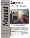
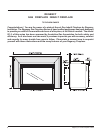
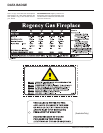
Regency I31-3 Gas Fireplace Inbuilt
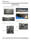
LOG SET
INSTALLATION
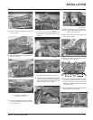
Read the instructions below carefully and
refer to the diagrams. If logs are broken
do not use the unit until they are replaced.
Broken logs can interfere with the pilot
operation.
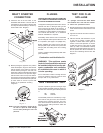
The gas log kit contains the following:
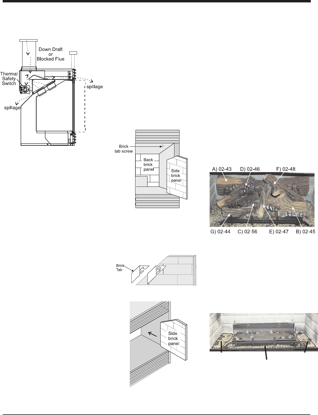
a) 02-43 Rear Log 902-227
b) 02-45 Front Right Log 902-229
c) 02-56 Middle Left Log 902-230
d) 02-46 Left Top Log 902-231
e) 02-47 Center Log 902-232
f) 02-48 Middle Right Log 902-226
g) 02-44 Front Left Log 902-228
h) Embers and Rockwool
i) Vermiculite and Ember combination
Note: Install Optional Brick Panels prior
to installing logs.
Vermiculite and
embers.
Vermiculite and
embers.
Vermiculite and
embers.
The "02" refer numbers (i.e. 02-43) are
molded into the rear of each log.
INSTALLATION
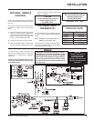
The smoke should be drawn into the spill tube.
If the smoke is still not drawn into the spill tube,
turn the unit off and check for the cause of the
lack of draft. If necessary, rectify.
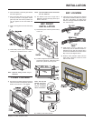
Diagram 1
Diagram 2
Diagram 3
For wind turbulent sites, a wind cap may rem-
edy the problem.
Note: The thermally activated safety
switch will sense the change in temper-
ature and shut down the gas valve in the
event of a severe downdraft or a blocked
or disconnected flue. The switch acts as
a safety shut-off to prevent a build-up of
carbon monoxide. If the flue is blocked or
has no "draw", the switch will automati-
cally shut off the supply of gas within 5 -
10 minutes. Tampering with the switch
can result in carbon monoxide (CO) poi-
soning and possible death.
If the heater turns off because of lack of
draft during the spillage test, check for
the cause and if necessary, rectify.
The thermally actuated safety switch will
automatically reset after it has cooled off.
The switch will continue to cycle until the
draft problem is corrected. DO NOT BY-
PASS OR DISCONNECT THIS SWITCH.
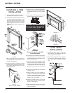
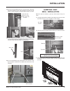
OPTIONAL
BRICK PANEL
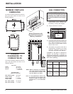
1) Unwrap the brick pattern panels from the
protective wrapping.
2) Remove the glass front if it is already
installed (see manual).
3) Put the rear brick panel flat against the back
of the unit.
4) Before installing the side brick panels, loos-
en the screws for the brick tabs enough so
that you can slide the brick tabs on to the
screws easily but that the tabs are secure.
For the location of the side brick tab screws
see diagram 1.
5) Remove the brick tabs and slide the side
brick panels into position. See diagram 3.
Install the brick tabs. See diagram 2.
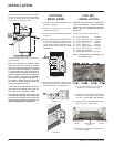
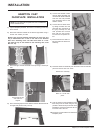
1) Carefully remove the logs from the box and
unwrap them. The logs are fragile, handle
with care - do not force into position.
2) Sprinkle the vermiculite and ember combi-
nation around the firebox base.
3) Place Rear Log A)02-43 on the two pins on
the rear log support.