


Special offers from our partners!

Find Replacement BBQ Parts for 20,308 Models. Repair your BBQ today.
6
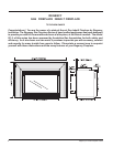
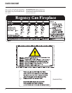
Regency I31-3 Gas Fireplace Inbuilt
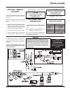
GAS CONNECTION
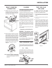
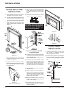
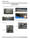
3) Locate the center point where the flue will
pass through the chimney above the appli-
ance. Move the appliance into the exact
location where it is to be installed. Ensure
that the Insert is level.
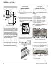
4) The installer must provide a valve with a
plugged tapping, accessible for test gauge
connection, immediately upstream of the
gas supply connection to the appliance.
CAUTION: If the glass is removed or
opened for servicing, it must be re-
placed and closed prior to operating the
appliance. The glass must be fixed in the
door when operating.
GAS CONNECTION WARNING:
Only persons licensed to work with
gas piping may make the neces-
sary gas connections to this appli-
ance.
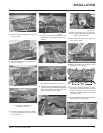
1) If the appliance is to be installed into an
existing chimney system, thoroughly clean
the masonry or factory built fireplace.
2) The gas connection is 12" BSP.
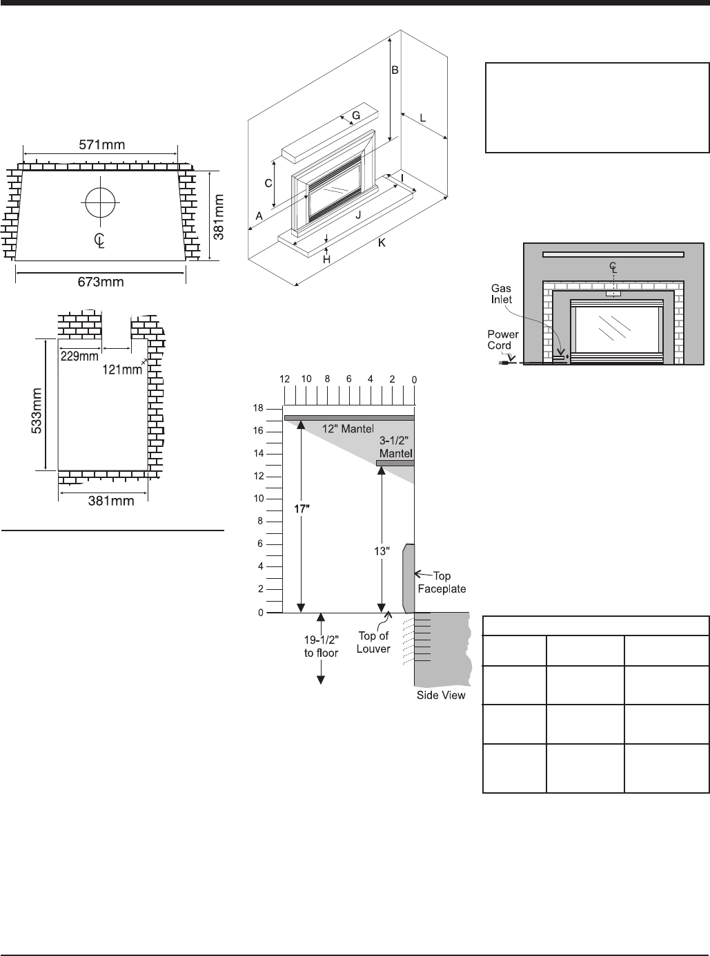
SPECIFICATIONS
INSTALLATION
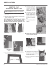
NOTE: Mantel clearances for Installation
into a Zero Clearance Kit are differ-
ent. Please refer to the Zero Clear-
ance Kit Manual for details.
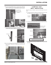
Mantel Clearances with
Bay and Flush Louvres in
Masonry Installation
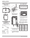
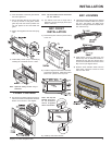
MINIMUM FIREPLACE
DIMENSIONS
The minimum fireplace dimensions for the Re-
gency gas space heater are shown in the
following diagrams:
Note: A non-combustible mantel may
be installed at a lower height if the
framing is made of metal studs
covered with a non-combustible
board.
MINIMUM
CLEARANCES TO
COMBUSTIBLES
The minimum fireplace clearances for the Re-
gency gas space heater are shown in the
following diagrams:
From Unit
Sides A 255 mm
Ceiling B 1205 mm
Mantle C see Mantel
Clearances
From Surround
(660 mm x 1016 mm)
Max. Mantle Depth G 305 mm
Hearth Height H 0 mm
Hearth Depth I 405 mm
Hearth Width J 1015 mm
Min. Alcove Width K 1220 mm
Max. Alcove Depth L 915 mm
NG LPG
INJECTOR #37 #52
SIZE 2.65mm 1.6mm
INPUT Min. 17 mj/h Min. 17 mj/h
RATING Max. 31 mj/h Max. 31 mj/h
MANIFOLD
PRESSURE Max. 0.9 kPa Max. 2.59 kPa