


Special offers from our partners!

Find Replacement BBQ Parts for 20,308 Models. Repair your BBQ today.
7
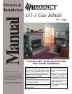
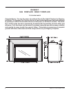
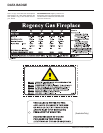
Regency I31-3 Gas Fireplace Inbuilt
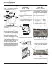
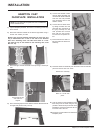
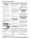
TEST FOR FLUE
SPILLAGE
A " spillage" test must be made before
the installed unit is left with the custom-
er. Follow the procedure below:
1) Start all exhaust fans in the home and then
close all external doors and windows in the
house.
2) Light the unit and set controls to maximum.
Turn fan off.
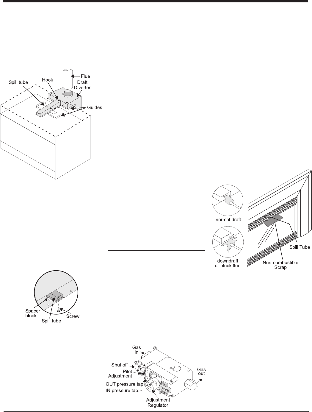
3) After five minutes, test that there is a “pull”
on the flue by placing a smoke match,
cigarette or similar device which gives off
smoke, in front of the spill tube. To ensure
a valid test, place a scrap piece of sheet
metal (or other noncombustible material)
between the spill tube and the upper louvre,
this will prevent the natural convection of
the unit from interfering with the test. See
diagram 1.
Diagram 1
INSTALLATION
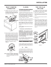
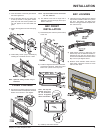
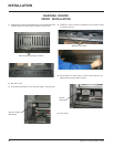
DRAFT DIVERTER
CONNECTION
1) Attach the flue to the flue collar on the
detachable draft diverter. The flue collar of
the appliance will fit inside a standard flue
and may be fastened directly to the flue by
sheet metal screw. Diagram 1.
NOTE: Final gas connection should be af-
ter unit is in place to avoid damage
to line when pushing the unit into
position.
Diagram 1
Diagram 2
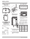
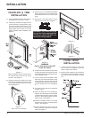
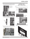
FLUEING
THE APPLIANCE MUST NOT BE CONNECTED
TO A CHIMNEY FLUE SERVING A SEPARATE
SOLID FUEL BURNING APPLIANCE.
This appliance is designed to attach to a 100 mm
diameter twin skin or listed gas fuel type flue
liner running the full length of the chimney. A
minimum flue height of 3.6 m. is recommended.
The Regency Inbuilt Fireplace incorporates its
own internal draft diverter, so no additional
external draftdiverter is required.
Periodically check that the flue is unrestricted
and an adequate draft is present when the unit
is in operation. (See page 7 for spillage test.)
Before installing flue system ensure that the
damper plate is open and secure to prevent the
damper plate from falling down and crushing
the liner.
Install to AS5601-2004,(Australia) NZS 5261
(New Zealand).
Combustion and Ventilation Air
WARNING: This appliance needs
fresh air for safe operation and must
be installed with provisions for ade-
quate combustion and ventilation
air available to the room in which it
is to be operating.
Air for combustion is drawn in through the front
of the unit, therefore, the front of the unit must
be kept clear of any obstructions.
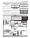
GAS PRESSURE TEST
The unit is preset to give the correct gas input
at the specified manifold pressures shown on
the label. The maximum gas manifold pressure
is:
NG 0.9 kPa
LPG 2.65 kPa
The manifold pressure is controlled by a regu-
lator built into the gas control, and should be
checked at the pressure test point. The pres-
sure check should be carried out with the unit
burning and the setting should be within the
limits specified.
2) Before pushing the appliance into position
inside the fireplace, align the draft diverter
with the guides on the insert top and push
forward. While pushing the unit back into
place keep pulling the draft diverter forward
until the screw hole in the spill tube aligns
with the screw hole in the top of the firebox.
The screw is secured through the inside top
of the firebox into the bottom of the spill tube.
(If screw holes do not line up then draft
diverter is not positioned correctly.)
Diagram 2.