


Special offers from our partners!

Find Replacement BBQ Parts for 20,308 Models. Repair your BBQ today.
*1 The total load current of resistance loads per common terminal
should be the following value or less.
- 1 output point/common terminal : 0.5A
- 4 output point/common terminal : 0.8A
- 8 output point/common terminal : 1.6A
As for the number of outputs per common terminal, refer to
“Chapter 4 interpretation of partition” and the following manual.
→ Refer to FX3U Series User's Manual - Hardware Edition.
*2 The total load current of resistance loads per common terminal
should be the following value or less.
- 4 output points/common terminal : 2A
As for the number of outputs per common terminal, refer to the
following manual.
→ Refer to FX3U Series User's Manual - Hardware Edition.
*3 The total load current of resistance loads per common terminal
should be the following value or less.
- 16 output point/common terminal : 1.6A
As for the number of outputs per common terminal, refer to the
following manual.
→Refer to FX3U Series User's Manual - Hardware Edition.
*4 The total of inductive loads per common terminal should be the
following value or less.
- 1 output point/common terminal : 12W/24V DC
- 4 output points/common terminal : 19.2W/24V DC
- 8 output points/common terminal : 38.4W/24V DC
As for the number of outputs per common terminal, refer to
“Chapter 4 interpretation of partition” and the following manual.
→ Refer to FX3U Series User's Manual - Hardware Edition.
*5 The total of inductive loads per common terminal should be the
following value or less.
- 4 output points/common terminal : 48W/24V DC
As for the number of outputs per common terminal, refer to the
following manual.
→ Refer to FX3U Series User's Manual - Hardware Edition.
*6 The total of inductive loads per common terminal should be the
following value or less.
- 16 output points/common terminal : 38.4W
As for the number of outputs per common terminal, refer to the
following manual.
→ Refer to FX3U Series User's Manual - Hardware Edition.
*7 The response time is as follows in the FX2N-8EYT-H.
-OFF→ON : 0.2ms or less/1A
-ON→OFF : 0.4ms or less/1A
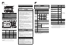
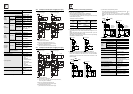
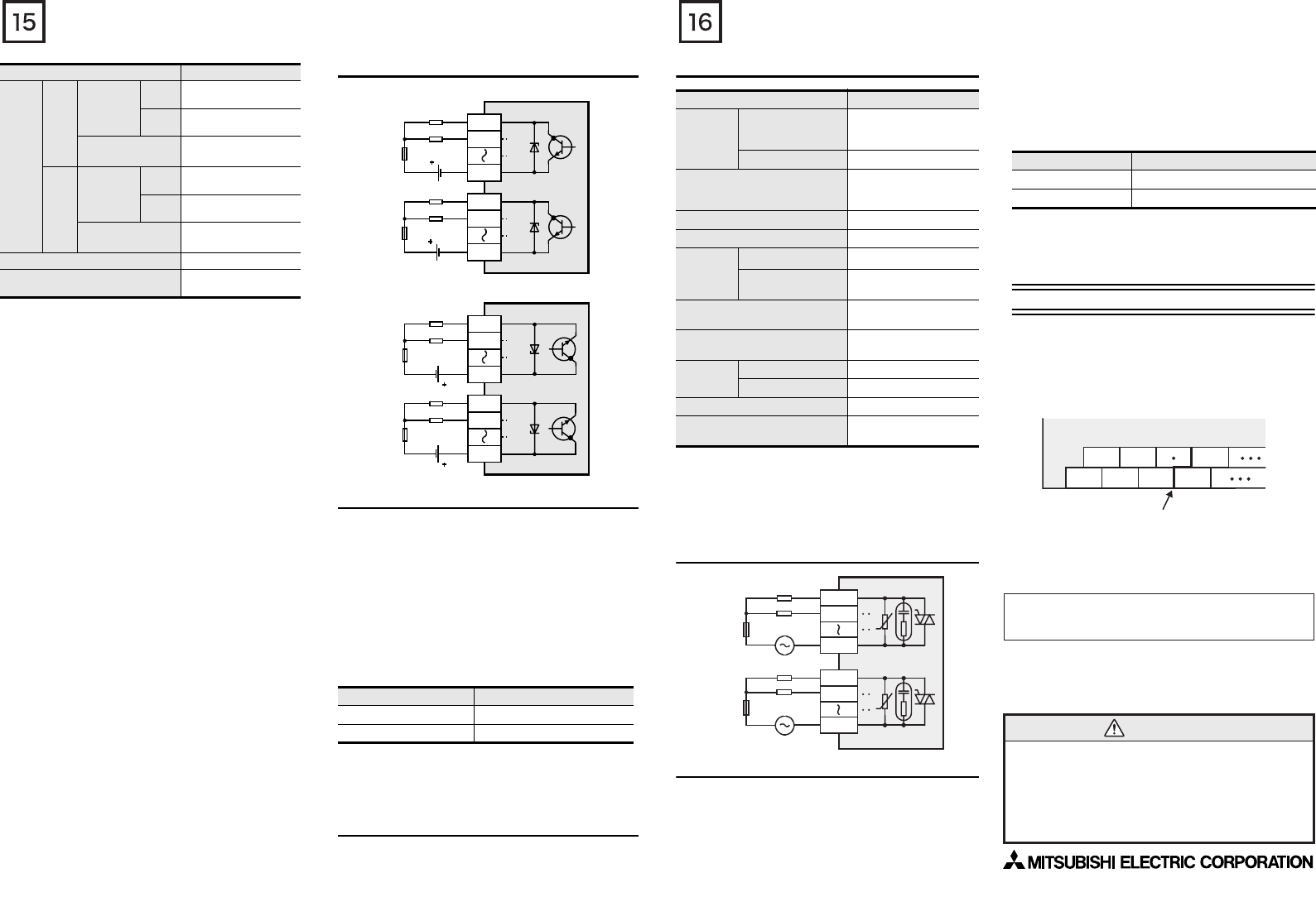
3.6.2 External Wiring of Transistor Output
1. External Wiring of Sink Output Type
2. External Wiring of Source Output Type
3.6.3 Cautions in external wiring
For cautions in external wiring, refer to the following manual.
→ Refer to FX3U Series User's Manual - Hardware Edition.
Protection circuit for load short-circuits
A short-circuit at a load connected to an output terminal could cause
burnout at the output element or the PCB. To prevent this, a
protection fuse should be inserted at the output.
Use a load power supply capacity that is at least 2 times larger than
the total rated fuse capacity.
Contact protection circuit for inductive loads
When an inductive load is connected, connect a diode (for
commutation) in parallel with the load as necessary.
The diode (for commutation) must comply with the following
specifications.
Interlock
Loads, such as contactors for normal and reverse rotations, that
must not be turned on simultaneously should have an interlock in the
PLC program and an external interlock.
3.7 Triac output specifications and example of
external wiring
As for the details of the triac output specifications and external
wiring, refer to the following manual.
→ Refer to FX3U Series User's Manual - Hardware Edition.
Respon
se time
OFF
→
ON
Main unit
Y000 to
Y002
5µs or less/10mA or more
(5 to 24V DC)
Y003 or
more
0.2ms or less/200mA
or more (at 24V DC)
Input/output extension
units/blocks
*7
0.2ms or less/200mA
or more (at 24V DC)
ON
→
OFF
Main unit
Y000 to
Y002
5µs or less/10mA or more
(5 to 24V DC)
Y003 or
more
0.2ms or less/200mA
or more (at 24V DC)
Input/output extension
units/blocks
*7
0.2ms or less/200mA
or more (at 24V DC)
Circuit insulation Photocoupler insulation
Display of output operation
LED on panel lights when
photocoupler is driven.
Item Specification
Item Guide
Reverse voltage 5 to 10 times of the load voltage
Forward current Load current or more
PLC
Load
24V DC
Fuse
Y000
Y001
COM1
Load
24V DC
Fuse
Y004
Y005
COM2
PLC
Load
24V DC
Fuse
Y000
Y001
+V0
Load
24V DC
Fuse
Y004
Y005
+V1
3.7.1 Triac output specifications
*1 The total load current of resistance loads per common terminal
should be the following value or less.
- 4 output points/common terminal : 0.8A
- 8 output points/common terminal : 0.8A
As for the number of outputs per common terminal, refer to
“Chapter 4 interpretation of partition” and the following manual.
→ Refer to FX3U Series User's Manual - Hardware Edition.
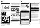
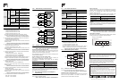
3.7.2 External Wiring of Triac Output
3.7.3 Cautions in external wiring
For cautions in external wiring, refer to the following manual.
→ Refer to FX3U Series User's Manual - Hardware Edition.
Protection circuit for load short-circuits
A short-circuit at a load connected to an output terminal could cause
burnout at the output element or the PCB. To prevent this, a
protection fuse should be inserted at the output.
Micro current load
The PLC's internal Triac output circuit is equipped with a turn-off C-R
absorber. When connecting a very low current load of "0.4VA/100V
AC or less, or 1.6VA/200V AC or less", please connect a surge
absorber parallel to the load.
Select the rated voltage of a surge absorber that is suitable for the
load being used. Refer to the table below for other specifications.
Interlock
Loads, such as contactors for normal and reverse rotations, that must
not be turned on simultaneously should have an interlock in the PLC
program and an external interlock.
4. Terminal block layouts
For details on the terminal block layout, refer to the following manual.
→ Refer to FX3U Series User's Manual - Hardware Edition.
Interpretation of partition
The partition of the output terminals (see following figure) indicates
the range of the output connected to the same common.
Item Specification
Number
of output
points
FX3U-32MS/ES
,
FX2N-16EYS
,
FX2N-32ES
16 points
FX3U-64MS/ES 32 points
Output connecting type
Refer to FX3U Series
User's Manual - Hardware
Edition
Output form Triac (SSR)
External power supply 85 to 242V AC
Max. load
Resistance load
0.3A/point
*1
Inductive load
15VA/100V AC,
30VA/200V AC
Min. load
0.4VA/100V AC,
1.6VA/200V AC
Open circuit leakage current
1mA/100V AC,
2mA/200V AC
Response
time
OFF→ON 1ms or less
ON→OFF 10ms or less
Circuit insulation Photo-thyristor insulation
Display of output operation
LED on panel lights when
photo-thyristor is driven.
PLC
U
U
Load
Fuse
AC power
supply
Fuse
Load
AC power
supply
Y000
Y001
COM1
Y005
Y004
COM2
Item Guide
Static electricity capacity Approx. 0.1µF
Resistance value Approx. 100 to 200Ω
Y0
Partition
Output terminal
Example: FX
3U
-48MT/ES
Y2
COM1 Y1 COM2Y3
Y4
This manual confers no industrial property rights or any rights of any other kind,
nor does it confer any patent licenses. Mitsubishi Electric Corporation cannot be
held responsible for any problems involving industrial property rights which may
occur as a result of using the contents noted in this manual.
Warranty
Mitsubishi will not be held liable for damage caused by factors found not to be
the cause of Mitsubishi; opportunity loss or lost profits caused by faults in the
Mitsubishi products; damage, secondary damage, accident compensation
caused by special factors unpredictable by Mitsubishi; damages to products
other than Mitsubishi products; and to other duties.
For safe use
This product has been manufactured as a general-purpose part for general
industries, and has not been designed or manufactured to be incorporated in
a device or system used in purposes related to human life.
Before using the product for special purposes such as nuclear power, electric
power, aerospace, medicine or passenger movement vehicles, consult with
Mitsubishi Electric.
This product has been manufactured under strict quality control. However
when installing the product where major accidents or losses could occur if the
product fails, install appropriate backup or failsafe functions in the system.
•
•
•
HEAD OFFICE
HIMEJI WORKS
: TOKYO BUILDING, 2-7-3 MARUNOUCHI, CHIYODA-KU, TOKYO 100-8310,
JAPAN
: 840, CHIYODA CHO, HIMEJI, JAPAN