


Special offers from our partners!

Find Replacement BBQ Parts for 20,308 Models. Repair your BBQ today.
2.2 Installation location
Install the PLC in an environment conforming to the generic
specifications (section 2.1), installation precautions and notes.
For more details, refer to FX
3U
Series User's Manual - Hardware
Edition.
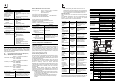
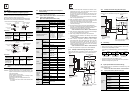
Installation location in enclosure
Space in enclosure
Extension devices can be connected on the left and right sides of the
main unit of the PLC.
If you intend to add extension devices in the future, keep necessary
spaces on the left and right sides.
2.2.1 Affixing The Dust Proof Sheet
The dust proof sheet should be affixed to the ventilation port before
beginning the installation and wiring work.
→ For the affixing procedure, refer to the instructions on the
dust proof sheet.
Be sure to remove the dust proof sheet when the installation and
wiring work is completed.
2.3 Procedures for installing to and detaching from
DIN rail
The products can be installed on a DIN46277 rail [35mm (1.38”)
wide]. This section explains the installations of the main units.
For the input/output extension units/blocks and special adapters,
refer to the following manual.
→ Refer to FX3U Series User’s Manual - Hardware Edition.
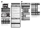
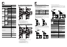
2.3.1 Installation
1) Connect the expansion boards and special adapters to the main
unit.
2) Push out all DIN rail mounting hooks (below fig.A)
3) Fit the upper edge of the DIN rail
mounting groove (right fig.C)
onto the DIN rail.
4) Lock the DIN rail mounting hooks (below fig.D) while pressing the
PLC against the DIN rail.
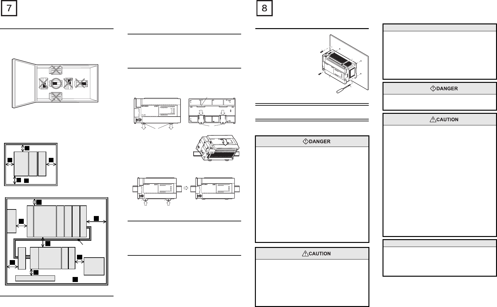
2.4 Procedures for installing directly (with M4
screws)
The product can be installed directly on the panel (with screws).
This section explains the installation of the main units.
As for the details of the installation/detaching for input extension
units/blocks and special adapters, refer to the following manual.
→ Refer to FX3U Series User's Manual - Hardware Edition.
2.4.1 Mounting hole pitches
Refer to the External Dimensions (section 1.2) for the product's
mounting hole pitch information.
As for the details of the mounting hole pitches for extension unit/
block and special adapters, refer to the following manual.
→ Refer to FX3U Series User's Manual - Hardware Edition.
≥
50mm (1.97")
A
A
A
A
A
FX
3U
Series
main
unit
FX
2N
-16EX
-ES/UL
FX
2N
-16EYT
-ESS/UL
Configuration without extension cable
Another equipment
Another
equipment
Extension
cable
·FX
0N
-65EC
·FX
0N
-30EC
Another
equipment
A
A
A
A
A
A
A
A
≥
50mm (1.97")
Configuration in 2 stages with extension cable
FX
2N
-CNV-BC
Input/output
powered
extension
unit
FX
2N
-16EX
-ES/UL
FX
2N
-10PG
FX
2N
-8AD
FX
3U
Series
main unit
FX
2N
-16EX-ES/UL
FX
2N
-16EYT-ESS/UL
FX
2N
-4AD
FX
2N
-16EYR-ES/UL
FX
3U
-4AD-ADP
A
2)2)
2)
A
2)
C
C
RUN
STOP
FX
3U
-48MR/ES
-48MR/ES
FX
3U
-48M
FX
3U
-48M
ERROR
RUN
BATT
POWER
0
3
1
2
IN
6
4
5
21
7
20
24
22
23
26
25
10
11
13
12
16
14
15
17
27
OUT
0
3
1
2
6
4
5
21
7
20
24
22
23
26
25
10
11
13
12
16
14
15
17
27
FX
3U
-48M
ERROR
RUN
BATT
POWER
R
0312
IN
OUT
645
21
7
20 2422 23 2625
1011 1312 161415 17
27
0312 645
21
7
20 2422 23 2625
1011 1312 161415 17
27
Y12Y10 Y16Y14 Y22Y20 Y26COM5
COM1
Y24Y6
Y4Y2Y0
Y7 Y11 Y13Y5
COM2
Y3
Y1
COM3 Y15 Y17COM4 Y23Y25 Y27Y21
X5
X0
X1
X2
X3 X7
X11
X13
X40VS/S
N24V
X6 X10 X12X14 X16X20
L X27X23 X25X15X17 X21
X24 X26X22
FX
3U
-48M
ERROR
RUN
BATT
POWER
R
0312
IN
OUT
645
21
7
20 2422 23 2625
1011 1312 161415 17
27
0312 645
21
7
20
24
2223
2625
1011 1312 161415 17
27
Y12Y10 Y16Y14 Y22Y20 Y26COM5
COM1
Y24Y6
Y4Y2Y0
Y7 Y11 Y13Y5
COM2
Y3
Y1
COM3 Y15 Y17COM4 Y23Y25 Y27Y21
X5
X0
X1
X2
X3 X7
X11
X13
X40VS/S
N24V
X6 X10 X12X14 X16X20
L
X27X23 X25X15X17 X21
X24 X26X22
FX
3U
-48M
ERROR
RUN
BATT
POWER
R
0 312
IN
OUT
645
21
7
20 2422 23 2625
1011 1312
12
1614 15 17
27
0 312 645
21
7
20 2422 23 2625
1011 1312
12
1614 15 17
27
Y12Y10
Y10
Y16Y14 Y22Y20 Y26COM5
COM1
Y24Y6
Y4Y2Y0
Y7 Y11 Y13Y5
COM2
Y3
Y1
COM3
COM3
Y15 Y17
Y17
COM4
COM4
Y23 Y25Y27Y21
Y21
X5
X0
X1
X2
X3 X7
X11
X13
X13
X40VS/S
N 24V
X6 X10 X12X14
X14
X16 X20
L X27X23 X25X15X17 X21
X24 X26X22
FX
3U
-48M
ERROR
RUN
BATT
POWER
R
0312
IN
OUT
645
21
7
20 2422 23 2625
1011 1312 161415 17
27
0312 645
21
7
20 2422 23 2625
1011 1312 161415 17
27
Y12Y10 Y16Y14 Y22Y20 Y26COM5
COM1
Y24Y6
Y4Y2Y0
Y7 Y11 Y13Y5
COM2
Y3
Y1
COM3 Y15 Y17COM4 Y23Y25 Y27Y21
X5
X0
X1
X2
X3 X7
X11
X13
X40VS/S
N 24V
X6 X10 X12X14 X16X20
L
X27X23 X25X15X17 X21
X24 X26X22
D
4)
D
4)
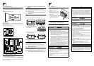
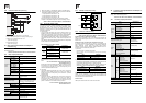
2.4.2 Installation
1) Make mounting holes in the
mounting surface referring to
the external dimensions
diagram.
2) Fit the main unit (A in the right
figure) based on the holes, and
secure it with M4 screws (B in
the right figure).
The mounting hole pitches and
number of screws depend on
the product. Refer to the
external dimensions diagram.
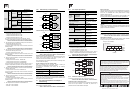
3. Power supply/input/output specifications
and examples of external wiring
As for the details of the power supply wiring and input/output wiring,
refer to FX3U Series User's Manual - Hardware Edition.
DESIGN
PRECAUTIONS
• Make sure to have the following safety circuits outside of the
PLC to ensure safe system operation even during external
power supply problems or PLC failure.
Otherwise, malfunctions may cause serious accidents.
1) Most importantly, have the following: an emergency stop
circuit, a protection circuit, an interlock circuit for opposite
movements (such as normal vs. reverse rotation), and an
interlock circuit (to prevent damage to the equipment at the
upper and lower positioning limits).
2) Note that when the PLC CPU detects an error, such as a
watchdog timer error, during self-diagnosis, all outputs are
turned off. Also, when an error that cannot be detected by
the PLC CPU occurs in an input/output control block,
output control may be disabled.
External circuits and mechanisms should be designed to
ensure safe machinery operation in such a case.
3) Note that when an error occurs in a relay, triac or transistor
output device, the output could be held either on or off.
For output signals that may lead to serious accidents,
external circuits and mechanisms should be designed to
ensure safe machinery operation in such a case.
DESIGN
PRECAUTIONS
• Do not bundle the control line together with or lay it close to the
main circuit or power line. As a guideline, lay the control line at
least 100mm (3.94") or more away from the main circuit or
power line.
Noise may cause malfunctions.
• Install module so that excessive force will not be applied to the
built-in programming connectors, power connectors or I/O
connectors.
Failure to do so may result in wire damage/breakage or PLC
failure.
FX
3U
-48MFX
3U
RUN
POWER
ERROR
BATT
FX
3U
-48MFX
3U
ERROR
RUN
BATT
POWER
0
3
1
2
IN
OUT
6
4
5
21
7
20
24
22
23
26
25
10
11
13
12
16
14
15
17
27
0
3
1
2
6
4
5
21
7
20
24
22
23
2625
10
11
13
12
16
14
15
17
27
B
A
B
Notes
• Simultaneously turn on and off the power supplies of the main
unit and extension devices.
• Even if the AC power supply causes an instantaneous power
failure for less than 10 ms, the PLC can continue to operate.
• Even if the DC power supply causes an instantaneous power
failure for less than 5ms, the PLC can continue to operate.
• If a long-time power failure or an abnormal voltage drop occurs,
the PLC stops, and output is turned off. When the power
supply is restored, it will automatically restart (when the RUN
input is on).
WIRING
PRECAUTIONS
• Cut off all phases of the power supply externally before
installation or wiring work in order to avoid damage to the
product or electric shock.
WIRING
PRECAUTIONS
• Connect the AC power supply to the dedicated terminals
specified in this manual.
If an AC power supply is connected to a DC input/output
terminal or DC power supply terminal, the PLC will burn out.
• Do not wire vacant terminals externally.
Doing so may damage the product.
• Use class D grounding (grounding resistance of 100Ω or less)
with a wire of 2mm
2
or thicker on the grounding terminal of the
FX3U Series main unit.
However, do not connect the ground terminal at the same point
as a heavy electrical system.
• When drilling screw holes or wiring, make sure cutting or wire
debris does not enter the ventilation slits.
Failure to do so may cause fire, equipment failures or
malfunctions.
• Make sure to properly wire to the terminal in accordance with
the following precautions.
Failure to do so may cause electric shock, equipment failures, a
short-circuit, wire breakage, malfunctions, or damage to the
product.
- The disposal size of the cable end should follow the
dimensions described in the manual.
- Tightening torque should follow the specifications in the
manual.
Notes
• Input/output wiring 50 to 100 m (164’1” to 328’1”) long will
cause almost no problems of noise, but, generally, the wiring
length should be less than 20 m (65’7”) to ensure the safety.
• Extension cables are easily affected by noise. Lay the cables
at a distance of at least 30 to 50 mm (1.19” to 1.97”) away from
the PLC output and other power lines.