


Special offers from our partners!

Find Replacement BBQ Parts for 20,308 Models. Repair your BBQ today.
Requirement for Compliance with LVD directive
The following products have shown compliance through direct
testing (of the identified standards below) and design analysis
(through the creation of a technical construction file) to the European
Directive for Low Voltage (2006/95/EC) when used as directed by
the appropriate documentation.
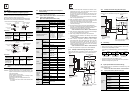
Type : Programmable Controller (Open Type Equipment)
Models : MELSEC FX3U series manufactured
from May 1st, 2005 FX3U-MR/ES(-A)
Where indicates:16,32,48,64,80
from November 1st, 2005 FX3U-MT/ES(-A)
FX3U-MT/ESS
Where indicates:16,32,48,64,80
from February 1st, 2006 FX3U-128MR/ES(-A)
FX3U-128MT/ES(-A)
FX3U-128MT/ESS
FX3U-MR/DS
Where indicates:16,32,48,64,80
from September 1st, 2010
FX3U-MR/UA1
FX3U-MS/ES
Where indicates:32,64
Models :MELSEC FX2N series manufactured
from July 1st, 1997 FX2N-ER-ES/UL FX2N-ET-ESS/UL
Where indicates:32,48
FX2N-16EYR-ES/UL
from April 1st, 1998 FX2N-48ER-DS
from August 1st, 1998 FX2N-48ER-UA1/UL
from August 1st, 2005 FX2N-8ER-ES/UL FX2N-8EYR-ES/UL
from September 1st, 2010
FX2N-8EYR-S-ES/UL
For the products above, PLCs manufactured
before March 31st, 2002 are compliant with IEC1010-1
from April 1st, 2002 to April 30th, 2006 are compliant with EN61131-
2:1994+A11:1996+A12:2000
after May 1st, 2006 are compliant with EN61131-2:2007
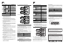
Caution for compliance with EC Directive
Installation in Enclosure
Programmable logic controllers are open-type devices that must be
installed and used within conductive control boxes. Please use the
FX3U Series programmable logic controllers while installed in
conductive shielded control boxes. Please secure the control box lid
to the control box (for conduction). Installation within a control box
greatly affects the safety of the system and aids in shielding noise
from the programmable logic controller.
Caution for Analog Products in use
The analog special adapters have been found to be compliant to the
European standards in the aforesaid manual and directive. However,
for the very best performance from what are in fact delicate
measuring and controlled output device Mitsubishi Electric would like
to make the following points;
As analog devices are sensitive by nature, their use should be
considered carefully. For users of proprietary cables (integral with
sensors or actuators), these users should follow those
manufacturers installation requirements.
Mitsubishi Electric recommend that shielded cables should be used.
If NO other EMC protection is provided, then users may experience
temporary induced errors not exceeding +10%/-10% in very heavy
industrial areas.
However, Mitsubishi Electric suggest that if adequate EMC
precautions are followed with general good EMC practice for the
users complete control system, users should expect normal errors
as specified in this manual.
- Sensitive analog cable should not be laid in the same trunking
or cable conduit as high voltage cabling. Where possible users
should run analog cables separately.
- Good cable shielding should be used. When terminating the
shield at Earth - ensure that no earth loops are accidentally
created.
Standard Remark
EN61000-6-4:2007
- Generic emission
standard
Industrial environment
EN50081-2:1993
Electromagnetic
compatibility
Compliance with all relevant aspects
of the standard.
• Emission-Enclosure port
• Emission-Low voltage AC mains
port
• Emission-Telecommunications/
network port
EN50082-2:1995
Electromagnetic
compatibility
- Generic immunity
standard
Industrial environment
Compliance with all relevant aspects
of the standard.
• RF immunity
• Fast Transients
• ESD
• Conducted
• Power magnetic fields
EN61131-2:1994
/A11:1996
/A12:2000
Programmable controllers
-Equipment
requirements and tests
Compliance with all relevant aspects
of the standard.
• Radiated electromagnetic field
• Fast transient burst
• Electrostatic discharge
• Damped oscillatory wave
EN61131-2:2007
Programmable controllers
-Equipment
requirements and tests
Compliance with all relevant aspects
of the standard.
EMI
• Radiated Emission
• Conducted Emission
EMS
• Radiated electromagnetic field
• Fast Transient burst
• Electrostatic discharge
• High-energy surge
• Voltage drops and interruptions
• Conducted RF
• Power frequency magnetic field
Standard Remark
EN61131-2:2007
Programmable controllers
-Equipment
requirements and tests
The equipment has been assessed
as a component for fitting in a
suitable enclosure which meets the
requirements of EN61131-2:2007
Standard Remark
IEC1010-1:1990
/A1:1992
Safety requirements for
electrical equipment for
measurement, control, and
laboratory use
- General requirements
The equipment has been assessed
as a component for fitting in a
suitable enclosure which meets the
requirements of IEC 1010-1:
1990+A1:1992
EN61131-2:1994 :2007
/A12:2000
/A11:1996
Programmable controllers
- Equipment
requirements and tests
The equipment has been assessed
as a component for fitting in a
suitable enclosure which meets the
requirements of EN61131-2:
1994+A11:1996+A12:2000, :2007
- When reading analog values, EMC induced errors can be
smoothed out by averaging the readings. This can be achieved
either through functions on the analog special adapter/block or
through a users program in the FX3U Series PLC main unit.
Associated manuals
FX3U Series PLC (main unit) comes with this document (hardware
manual).
For a detailed explanation of the FX3U Series hardware and
information on instructions for PLC programming and special
extension unit/block, refer to the relevant documents.
How to obtain manuals
For the necessary product manuals or documents, consult with the
Mitsubishi Electric dealer from where you purchase your product.
Incorporated Items
Check if the following product and items are included in the package:
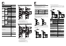
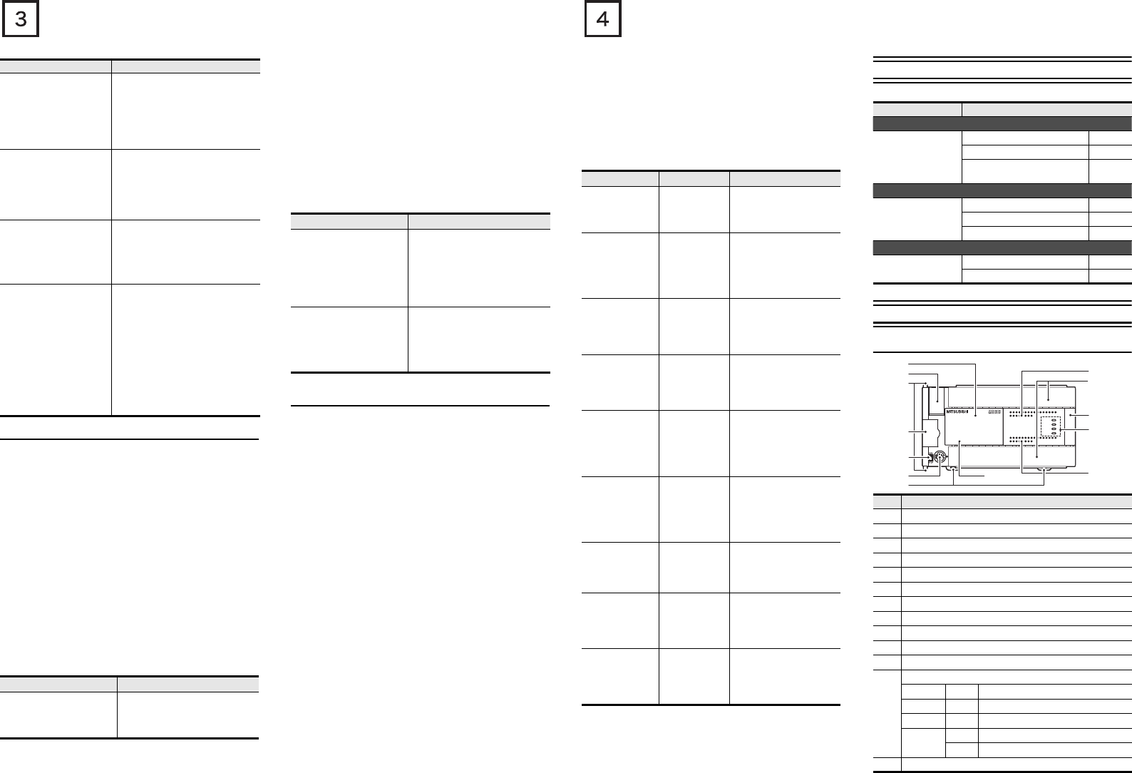
1. Outline
1.1 Part names
Manual name Manual No. Description
FX3U Series
User's Manual
- Hardware
Edition
JY997D16501
MODEL CODE:
09R516
Explains FX3U Series PLC
specification details for I/O,
wiring, installation, and
maintenance.
FX3G/FX3U/
FX3UC Series
Programming
Manual
- Basic & Applied
Instruction Edition
JY997D16601
MODEL CODE:
09R517
Describes PLC
programming for basic/
applied instructions STL/
SFC programming and
devices.
MELSEC-Q/L/F
Structured
Programming
Manual
(Fundamentals)
SH-080782
MODEL CODE:
13JW06
Programming methods,
specifications, functions,
etc. required to create
structured programs.
FXCPU
Structured
Programming
Manual
[Device & Common]
JY997D26001
MODEL CODE:
09R925
Devices, parameters, etc.
provided in structured
projects of GX Works2.
FXCPU
Structured
Programming
Manual
[Basic & Applied
Instruction]
JY997D34701
MODEL CODE:
09R926
Sequence instructions
provided in structured
projects of GX Works2.
FXCPU
Structured
Programming
Manual
[Application
Functions]
JY997D34801
MODEL CODE:
09R927
Application functions
provided in structured
projects of GX Works2.
FX Series User’s
Manual - Data
Communication
Edition
JY997D16901
MODEL CODE:
09R715
Explains N:N link, parallel
link, computer link, no
protocol communication by
RS instructions/FX2N-
232IF.
FX3G/FX3U/
FX3UC Series
User's Manual
- Analog Control
Edition
JY997D16701
MODEL CODE:
09R619
Describes specifications for
analog control and
programming methods for
FX3G/FX3U/FX3UC Series
PLC.
FX3G/FX3U/
FX
3UC Series
User's Manual
- Positioning
Control Edition
JY997D16801
MODEL CODE:
09R620
Explains the specifications
for positioning control of
FX
3G/FX3U/FX3UC Series
and programming
procedures
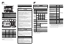
Included Items
Main units
FX3U-16M to
FX3U-128M
Product 1 unit
Dust proof protection sheet 1 sheet
Manuals [Japanese version,
English version]
1 manual
each
Input/output extension units
FX2N-32E,
FX2N-48E
Product 1 unit
Extension cable 1 cable
Input/output number label 1 sheet
Input/output extension blocks
FX2N-8E,
FX2N-16E
Product 1 unit
Input/output number label 1 sheet
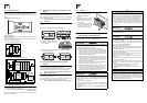
No. Name
[1] Top cover
[2] Battery cover
[3] Special adapter connecting hooks (2 places)
[4] Expansion board dummy cover
[5] RUN/STOP switch
[6] Peripheral device connecting connector
[7] DIN rail mounting hooks
[8] Model name (abbreviation)
[9] Input display LEDs (Red)
[10] Terminal block covers
[11] Extension device connecting connector cover
[12]
Operation status display LEDs
POWER Green On while power is on the PLC.
RUN Green On while the PLC is running.
BATT Red Lights when the battery voltage drops.
ERROR
Red Flashing when a program error occurs.
Red Lights when a CPU error occurs.
[13] Output display LEDs (Red)
FX
3U
-48MR/ES
FX
3U
-48MFX
3U
ERROR
RUN
BATT
POWER
R
0312
IN
OUT
645
21
7
20 242223 2625
1011 1312 161415 17
27
0312 645
21
7
20 242223 2625
1011 1312 161415 17
27
Y12Y10 Y16Y14 Y22Y20 Y26 COM5
COM1
Y24Y6
Y4Y2Y0
Y7 Y11 Y13Y5
COM2
Y3
Y1
COM3 Y15 Y17COM4 Y23 Y25 Y27Y21
X5
X0
X1
X2
X3 X7
X11
X13
X40VS/S
N24V
X6 X10 X12 X14 X16 X20
L X27X23 X25X15 X17 X21
X24 X26X22
FX
3U
-48MR/ES
FX
3U
-48MFX
3U
ERROR
RUN
BATT
POWER
R
0312
IN
OUT
645
21
7
20 242223 2625
1011 1312 161415 17
27
0312 645
21
7
20 242223 2625
1011 1312 161415 17
27
Y12Y10 Y16Y14 Y22Y20 Y26 COM5
COM1
Y24Y6
Y4Y2Y0
Y7 Y11 Y13Y5
COM2
Y3
Y1
COM3 Y15 Y17COM4 Y23 Y25 Y27Y21
X5
X0
X1
X2
X3 X7
X11
X13
X40VS/S
N24V
X6 X10 X12 X14 X16 X20
L
X27X23 X25X15 X17 X21
X24 X26X22
[1]
[2]
[3]
[9]
[10]
[11]
[12]
[13]
[8]
[4]
[5]
[6]
[7]