


Special offers from our partners!

Find Replacement BBQ Parts for 20,308 Models. Repair your BBQ today.
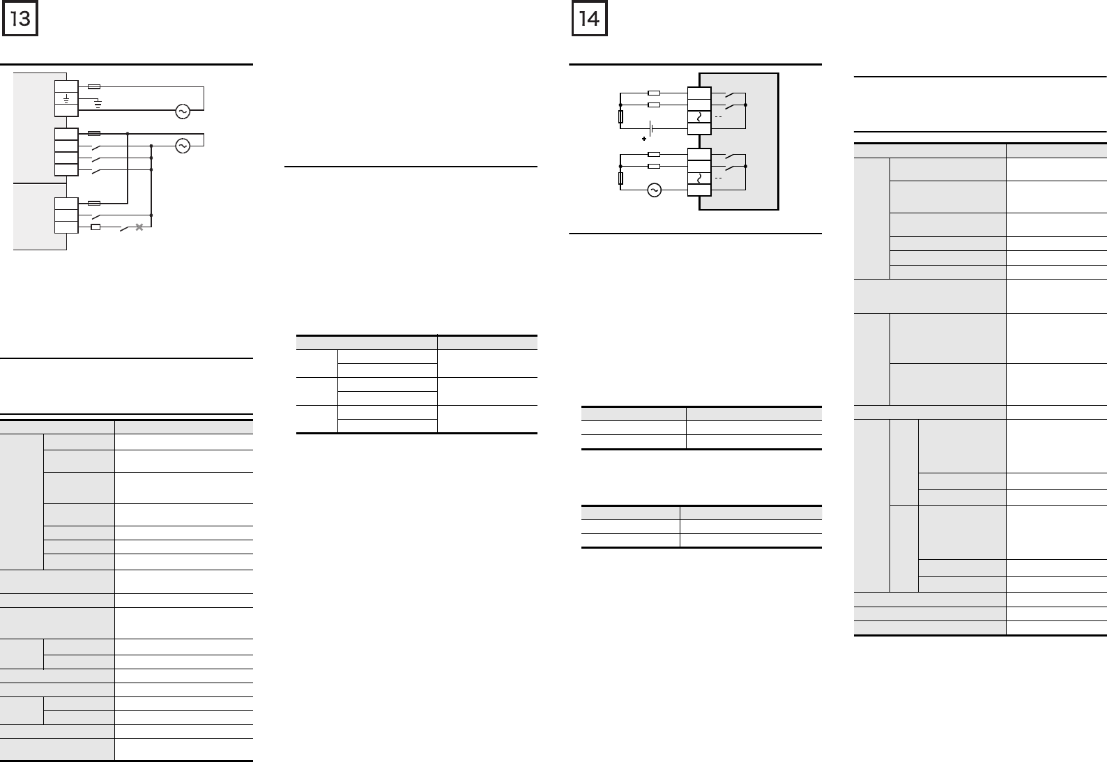
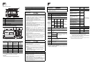
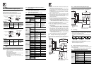
3.4.6 Examples of 100V AC input wiring
3.5 Relay output specifications and example of
external wiring
As for the details of Instructions for connecting input devices, refer to
the following manual.
→ Refer to FX3U Series User's Manual - Hardware Edition.
3.5.1 Relay output specifications
*1 Each value inside ( ) indicates the number of occupied points.
*2 The total load current of resistance loads per common terminal
should be the following value or less.
- 1 output points/common terminal : 2A
- 4 output points/common terminal : 8A
- 8 output points/common terminal : 8A
As for the number of outputs per common terminal, refer to
“Chapter 4 interpretation of partition” and the following manual.
→ Refer to FX3U Series User's Manual - Hardware Edition.
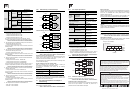
3.5.2 Life of relay output contact
The product life of relay contacts considerably varies depending on
the load type used. Take care that loads generating reverse
electromotive force or rush current may cause poor contact or
deposition of contacts which may lead to considerable reduction of
the contact product life.
1) Inductive load
Inductive loads generate large reverse electromotive force
between contacts at shutdown which may cause arcing. At a
fixed current consumption, as the power factor (phase between
current and voltage) gets smaller, the arc energy gets larger.
The standard life of the contact used for Inductive loads, such as
contactors and solenoid valves, is 500 thousand operations at
20VA.
The following table shows the approximate life of the relay based
on the results of our operation life test.
Test condition: 1 sec. ON / 1 sec.OFF.
The product life of relay contacts becomes considerably shorter
than the above conditions when the rush overcurrent is shut
down.
→ For countermeasures while using inductive loads,
refer to Subsection 3.5.4.
Some types of inductive loads generate rush current 5 to 15 times
the stationary current at activation. Make sure that the rush
current does not exceed the current corresponding to the
maximum specified resistance load.
2) Lamp load
Lamp loads generally generate rush current 10 to 15 times the
stationary current. Make sure that the rush current does not
exceed the current corresponding to the maximum specified
resistance load.
3) Capacitive load
Capacitive loads can generate rush current 20 to 40 times the
stationary current. Make sure that the rush current does not
exceed the current corresponding to the maximum specified
resistance load. Capacitive loads such as capacitors may be
present in electronic circuit loads including inverters.
→ For the maximum specified resistance load,
refer to Subsection 3.5.1.
Item Specification
Number of
output
points
FX2N-8ER
4 points (8 points)
*1
FX3U-16MR
,
FX2N-8EYR
8 points
FX3U-32MR/
,
FX
2N-32ER
,
FX2N-16EYR
16 points
FX3U-48MR
,
FX
2N-48ER
24 points
FX3U-64MR/
32 points
FX3U-80MR
40 points
FX
3U
-128MR/ES
64 points
Output connecting type
Refer to FX3U Series User's Manual
- Hardware Edition
Output form Relay
External power supply
30V DC or less
240V AC or less ("250V AC or less" if
not a CE, UL, cUL compliant item)
Max. load
Resistance load
2A/point
*2
Inductive load
80VA
Min. load 5V DC, 2mA (reference value)
Open circuit leakage current -
Response
time
OFF→ON Approx. 10ms
ON→OFF Approx. 10ms
Circuit insulation Mechanical insulation
Display of output operation
LED on panel lights when power is
applied to relay coil.
*1
*1 Class D grounding See section 3.3 for details.
*2 Do not take input signals from loads generating surge.
L
N
COM
X000
X001
X002
100-240V AC
100-120V AC
COM
X000
X001
MC
*2
Fuse
Fuse
Fuse
[1]
[2]
[1]:Main unit, Input/output extension unit
(100V AC input type)
[2]:Input extension block
(100V AC input type)
Load capacity Contact life
20VA
0.2A/100V AC
3 million times
0.1A/200V AC
35VA
0.35A/100V AC
1 million times
0.17A/200V AC
80VA
0.8A/100V AC
2 hundred thousand times
0.4A/200V AC
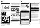
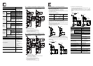
3.5.3 Example of relay output wiring
3.5.4 Cautions in external wiring
For cautions in external wiring, refer to the following manual.
→ Refer to FX3U Series User's Manual - Hardware Edition.
Protection circuit for load short-circuiting
When a load connected to the output terminal short-circuits, the
printed circuit board may be burnt out. Fit a protective fuse on the
output circuit.
Protection circuit of contact when inductive load is used
An internal protection circuit for the relays is not provided for the
relay output circuit. It is recommended to use inductive loads with
built-in protection circuits. When using loads without built-in
protection circuits, insert an external contact protection circuit, etc.
to reduce noise and extend the product life.
1) DC circuit
Connect a diode in parallel with the load.
Use a diode (for commutation) having the following
specifications.
2) AC circuit
Connect the surge absorber (combined CR components such as
a surge killer and spark killer, etc.) parallel to the load.
Select the rated voltage of the surge absorber suitable to the
output used. Refer to the table below for other specifications.
Interlock
Loads, such as contactors for normal and reverse rotations, that
must not be turned on simultaneously should have an interlock in the
PLC program and an external interlock.
Common mode
Use output contacts of the PLC in the common mode.
3.6 Transistor output specifications and example of
external wiring
As for the details of the transistor output specifications and external
wiring, refer to the following manual.
→ Refer to FX3U Series User's Manual - Hardware Edition.
3.6.1 Transistor output specifications
Item Standard
Reverse voltage 5 to 10 times the load voltage
Forward current Load current or more
Item Standard
Electrostatic capacity Approx. 0.1µF
Resistance value Approx. 100 to 200Ω
PLC
24V DC
Fuse
Y000
100V AC
COM1
Y001
Load
Fuse
Y010
COM2
Y011
Load
Item Specification
Number
of
output
points
FX3U-16MT/,
FX2N-8EYT
8 points
FX3U-32MT/,
FX2N-32ET,
FX2N-16EYT
16 points
FX3U-48MT/,
FX2N-48ET
24 points
FX3U-64MT/ 32 points
FX3U-80MT/ 40 points
FX3U-128MT/ES(S) 64 points
Output connecting type
Refer to FX3U Series
User's Manual -
Hardware Edition
Output
form
FX3U-MT/S(-A),
FX2N-ET,
FX2N-48ET-D,
FX2N-EYT,
FX2N-8EYT-H
Transistor(Sink)
FX3U-MT/SS,
FX2N-ET-ESS/UL,
FX2N-48ET-DSS,
FX2N-EYT-ESS/UL
Transistor(Source)
External power supply 5 to 30V DC
Max.
load
Resist
ance
load
FX3U-MT/,
FX2N-ET,
FX2N-ET-,
FX2N-EYT,
FX2N-EYT-ESS/UL
0.5A/point
*1
FX2N-8EYT-H
1A/point
*2
FX2N-16EYT-C
0.3A/point
*3
Induct
ive
load
FX3U-MT/,
FX2N-ET,
FX2N-ET-,
FX2N-EYT,
FX2N-EYT-ESS/UL
12W/24V DC
*4
FX2N-8EYT-H
24W/24V DC
*5
FX2N-16EYT-C
7.2W/24V DC
*6
Min. load −
Open circuit leakage current 0.1mA or less/30V DC
ON voltage 1.5V or less