


Special offers from our partners!

Find Replacement BBQ Parts for 20,308 Models. Repair your BBQ today.
3.1 Wiring
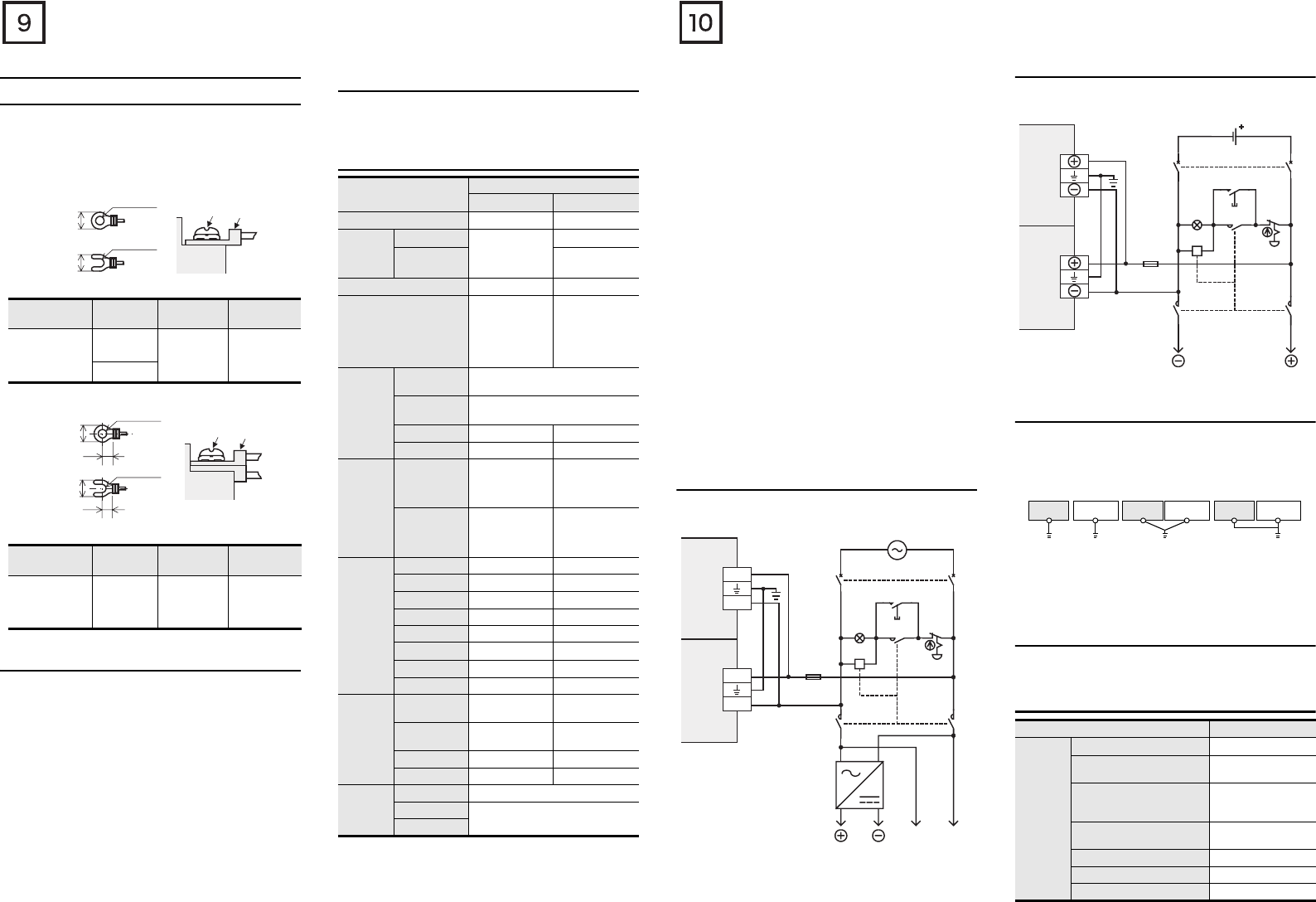
3.1.1 Cable end treatment and tightening torque
For the terminals of FX3U series PLC, M3 screws are used.
The electric wire ends should be treated as shown below.
Tighten the screws to a torque of 0.5 to 0.8 N
•
m.
Do not tighten terminal screws exceeding the specified torque.
Failure to do so may cause equipment failures or malfunctions.
• When one wire is connected to one terminal
<Reference>
• When two wires are connected to one terminal
<Reference>
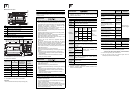
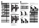
3.1.2 Removal and installation of quick-release terminal
block
Removal Unscrew the terminal block mounting screw [both right
and left screws] evenly, and remove the terminal block.
Installation Place the terminal block in the specified position, and
tighten the terminal block mounting screw evenly [both
right and left screws].
Tightening torque 0.4 to 0.5 N
•
m
Do not tighten the terminal block mounting screws
exceeding the specified torque.
Failure to do so may cause equipment failures or
malfunctions.
* Pay attention so that the center of the terminal block
is not lifted.
3.2 Power supply specifications and example of
external wiring
As for the details of the power supply specifications and example of
external wiring, refer to the following manual.
→ Refer to FX3U Series User's Manual - Hardware Edition.
3.2.1 Power supply specifications
[Main unit, Input/output extension units]
Terminal
Manufacturer
Type No. Certification
Pressure
Bonding Tool
JAPAN
SOLDERLESS
TERMINAL MFG
CO LTD (JST)
FV1.25-B3A
UL Listed YA-1(JST)
FV2-MS3
Terminal
Manufacturer
Type No. Certification
Pressure
Bonding Tool
JAPAN
SOLDERLESS
TERMINAL MFG
CO LTD (JST)
FV1.25-B3A UL Listed YA-1(JST)
φ3.2 (0.13")
6.2 mm (0.24")
or less
Terminal
screw
Solderless
terminal
6.2 mm (0.24")
or less
φ3.2 (0.13")
Terminal
6.3 mm(0.25")
or more
6.3 mm(0.25")
or more
6.2 mm (0.24")
or less
6.2 mm (0.24")
or less
φ3.2 (0.13")
φ3.2 (0.13")
Terminal
Terminal
screw
Solderless
terminal
Item
Specification
AC power type
DC power type
*6
Supply voltage 100 - 240V AC 24 V DC
Allowable
supply
voltage
range
Main unit
85 to 264V AC
16.8 to 28.8V DC
*5
FX2N-32E,
FX2N-48E
24V DC +20%,
-30%
Rated frequency 50/60Hz −
Allowable instantaneous
power failure time
Operation can be
continued upon
occurrence of
instantaneous
power failure for
10 ms or less.
*4
Operation can be
continued upon
occurrence of
instantaneous
power failure for 5
ms or less.
Power
fuse
FX3U-16M to
32M
*7
250V 3.15A
FX3U-48M to
128M
250V 5A
FX2N-32E 250V 3.15A -
FX2N-48E 250V 5A 250V 5A
Rush
current
Main unit
30A max. 5ms or
less/100V AC
65A max. 5ms or
less/200V AC
35A max. 0.5ms or
less/24V DC
FX2N-32E,
FX2N-48E
40A max. 5ms or
less/100V AC
60A max. 5ms or
less/200V AC
-
Power
consumption
*1
FX3U-16M 30W 25W
FX3U-32M 35W 30W
FX3U-48M 40W 35W
FX3U-64M 45W 40W
FX3U-80M 50W 45W
FX3U-128M
65W −
FX2N-32E 30W(35VA) −
FX2N-48E 35W(45VA) 30W
24V DC
service
power
supply
*2
FX3U-16M to
32M
400mA or less −
FX3U-48M to
128M
600mA or less −
FX2N-32E 250mA −
FX2N-48E 460mA −
5V DC
builtin
power
supply
*3
Main unit 500 mA or less
FX2N-32E
690mA or less
FX2N-48E
*1 Does not include the power consumption of extension units /
special extension units, and of the extension blocks / special
extension blocks connected to those units.
For the power (current) consumed by the extension units/
blocks for input/output, refer to FX3U Series User's Manual -
Hardware Edition.
For the power consumed by the special extension units/blocks,
refer to the appropriate manual.
*2 When input/output extension blocks are connected, the 24V
DC service power supply is consumed by the blocks, and the
current value to be used by the main unit is reduced.
The AC power (AC input) type and DC power type do not have
a service power supply.
*3 Cannot be used to supply power to an external destination.
The power is supplied to input/output extension blocks, special
extension blocks, special adapters and expansion boards.
The following manual shows further information.
→ Refer to FX3U Series User’s Manual - Hardware Edition.
*4 When the supply voltage is 200 V AC, the time can be changed
to 10 to 100 ms by editing the user program.
*5 When supply voltage is DC 16.8-19.2V, the connectable
extension equipment decreases. The following manual shows
further information.
→ Refer to FX3U Series User’s Manual - Hardware Edition.
*6 When attaching high-speed input/output special adapter
(FX3U-4HSX-ADP, FX3U-2HSY-ADP) and special function
block (FX0N-3A, FX2N-2AD, FX2N-2DA), the number of
connectable modules to the main unit is limited, due to the
current consumption (internal 24V DC) at startup. The following
manual shows further information.
→ Refer to FX3U Series User’s Manual - Hardware Edition.
*7 250V 5A is specified for the power fuse of FX3U-32MR/UA1.
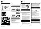
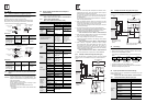
3.2.2 Example of external wiring (AC power type)
100 to 240V AC power is supplied to the main unit and input/output
extension units. For the details of wiring work, refer to section 3.1.
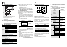
3.2.3 Example of external wiring (DC power type)
24V DC power is supplied to the main unit and input/output
extension unit. For the details of wiring work, refer to section 3.1.
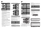
3.3 Grounding
Ground the PLC as stated below.
•
Perform class D grounding. (Grounding resistance: 100
Ω
or less)
•
Ground the PLC independently if possible.
If it cannot be grounded independently, ground it jointly as shown
below.
• Use ground wires thicker than AWG14 (2 mm
2
).
• Position the grounding point as close to the PLC as possible to
decrease the length of the ground wire.
3.4 Input specifications and external wiring
As for the details of the input specifications and external wiring, refer
to the following manual.
→ Refer to FX3U Series User's Manual - Hardware Edition.
3.4.1 Input specifications (24V DC input type)
Power on
100 to 240V AC
PL
MC
MC
DC AC
MCMC
Breaker
*
L
N
PLC
L
N
Main unit
Input/output
extension
unit
Emer-
gency
DC
power
supply
Power supply for loads connected
to PLC output terminals
Fuse
*Class D grounding
See section 3.3 for
details.
Item Specification
Number of
input
points
FX
2N
-8ER
4 points (8 points)
*1
FX
3U
-16M
,
FX
2N
-8EX
8 points
FX
3U
-32M
,
FX
2N
-16EX
,
FX
2N
-32E
16 points
FX
3U
-48M
,
FX
2N
-48E
24 points
FX
3U
-64M
32 points
FX
3U
-80M
40 points
FX
3U
-128M
64 points
24V DC
PL
Power on
Emer-
gency
MC
MC
Power supply for loads connected
to PLC output terminals
MCMC
* Class D grounding
See section 3.3 for
details.
Circuit protector
Fuse
*
PLC
Main unit
Input/output
extension
unit
PLC
Another
equipment
PLC
Another
equipment
PLC
Another
equipment
Shared grounding
(Good condition)
Common grounding
(Not allowed)
Independent grounding
(Best condition)