


Special offers from our partners!

Find Replacement BBQ Parts for 20,308 Models. Repair your BBQ today.
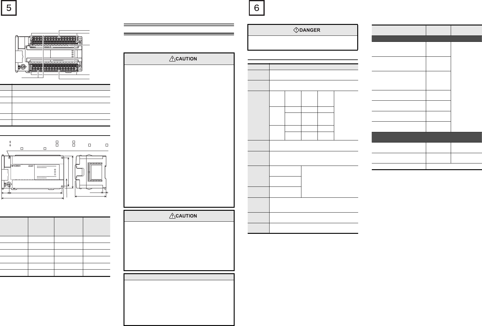
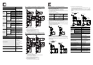
With terminal cover open
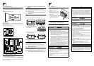
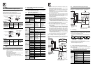
1.2 External dimensions and weight
*1 FX3U-32MR/UA1 uses 4-φ4.5 mounting holes.
*2 Except FX3U-32MR/UA1
*3 FX3U-32MR/UA1 is equivalent to FX3U-48M.
*4 FX3U-64MR/UA1 is equivalent to FX3U-80M.
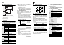
Installation
•35-mm-wide DIN rail or Direct (screw) mounting (M4)
2. Installation (general specifications)
As for installation of the input/output extension units/blocks, special
adapters and expansion boards, refer to FX3U Series User's Manual
- Hardware Edition.
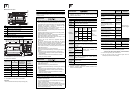
No. Name
[1] Protective terminal covers (FX3U-M/-A is excluded)
[2] Power supply, Input (X) terminals
[3]
Terminal block mounting screws
(FX3U-16M terminal block cannot be installed/removed)
[4] Terminal names
[5] Output (Y) terminals
Model name
W:
mm (inches)
W1:
mm (inches)
Direct mounting
hole pitches
MASS
(Weight)
:
kg (lbs)
FX3U-16M 130 (5.12”) 103 (4.06”) 0.6 (1.32lbs)
FX3U-32M
*3
150 (5.91”) 123 (4.85”) 0.65 (1.43lbs)
FX3U-48M 182 (7.17”) 155 (6.11”) 0.85 (1.87lbs)
FX3U-64M
*4
220 (8.67”) 193 (7.6”) 1.00 (2.2lbs)
FX3U-80M 285 (11.23”) 258 (10.16”) 1.20 (2.64lbs)
FX3U-128M
350 (13.78”) 323 (12.72”) 1.80 (3.96lbs)
FX
3U
-48MR/ES
FX
3U
-48MFX
3U
ERROR
RUN
BATT
POWER
R
0312
IN
OUT
645
21
7
20 242223 2625
1011 1312 161415 17
27
0312 645
21
7
20 242223 2625
1011 1312 161415 17
27
Y12Y10 Y16Y14 Y22Y20 Y26 COM5
COM1
Y24Y6
Y4Y2Y0
Y7 Y11 Y13Y5
COM2
Y3
Y1
COM3 Y15 Y17COM4 Y23 Y25 Y27Y21
X5
X0
X1
X2
X3 X7
X11
X13
X40VS/S
N 24V
X6 X10 X12 X14 X16 X20
L X27X23 X25X15 X17 X21
X24 X26X22
FX
3U
-48MR/ES
FX
3U
-48MFX
3U
ERROR
RUN
BATT
POWER
R
0312
IN
OUT
645
21
7
20 242223 2625
1011 1312 161415 17
27
0312 645
21
7
20 242223 2625 27
Y12Y10 Y16Y14 Y22Y20 Y26 COM5
COM1
Y24Y6
Y4Y2Y0
Y7 Y11 Y13Y5
COM2
Y3
Y1
COM3 Y15 Y17COM4 Y23 Y25 Y27Y21
X5
X0
X1
X2
X3 X7
X11
X13
X40VS/S
N 24V
X6 X10 X12 X14 X16 X20
L
X27X23 X25X15 X17 X21
X24 X26X22
[2]
[5]
[3]
[3]
[1]
[4]
FX
3U
-48MR/ES
FX
3U
-48MFX
3U
ERROR
RUN
BATT
POWER
R
0312
IN
OUT
645
21
7
20 242223 2625
1011 1312 161415 17
27
0312 645
21
7
20 242223 2625
1011 1312 161415 17
27
Y12Y10 Y16Y14 Y22Y20 Y26 COM5
COM1
Y24Y6
Y4Y2Y0
Y7 Y11 Y13Y5
COM2
Y3
Y1
COM3 Y15 Y17COM4 Y23 Y25 Y27Y21
X5
X0
X1
X2
X3 X7
X11
X13
X40VS/S
N 24V
X6 X10 X12 X14 X16 X20
L X27X23 X25X15 X17 X21
X24 X26X22
FX
3U
-48MFX
3U
ERROR
RUN
BATT
POWER
R
0312
IN
OUT
645
21
7
20 242223 2625
1011 1312 161415 17
27
0312 645
21
7
20 242223 2625
1011 1312 161415 17
27
Y12Y10 Y16Y14 Y22Y20 Y26 COM5
COM1
Y24Y6
Y4Y2Y0
Y7 Y11 Y13Y5
COM2
Y3
Y1
COM3 Y15 Y17COM4 Y23 Y25 Y27Y21
X5
X0
X1
X2
X3 X7
X11
X13
X40VS/S
N 24V
X6 X10 X12 X14 X16 X20
L
X27X23 X25X15 X17 X21
X24 X26X22
W
W1
22
(0.87")
Unit:mm(inches)
90(3.55")
80(3.15")
86(3.39")
2- 4.5-diam mounting holes (FX
3U
-16M , FX
3U
-32M )
4- 4.5-diam mounting holes (FX
3U
-48M , FX
3U
-64M ,FX
3U
-80M ,FX
3U
-128M )
FX
3U
-16M and FX
3U
-32M do not have the (*)-marked mounting holes.
9(0.36")
Mounting hole pitches
*
*
*
1
*
2
INSTALLATION
PRECAUTIONS
•
Use the product within the generic environment specifications
described in section 2.1 of this manual.
Never use the product in areas with excessive dust, oily smoke,
conductive dusts, corrosive gas (salt air, Cl
2
, H
2
S, SO
2
or NO
2
),
flammable gas, vibration or impacts, or exposed to high
temperature, condensation, or rain and wind.
If the product is used in such conditions, electric shock, fire,
malfunctions, deterioration or damage may occur.
•
Do not touch the conductive parts of the product directly to avoid
failure or malfunctions.
•
Install the product securely using a DIN rail or mounting screws.
• Install the product on a flat surface.
If the mounting surface is rough, undue force will be applied to
the PC board, thereby causing nonconformities.
• When drilling screw holes or wiring, make sure cutting or wire
debris does not enter the ventilation slits.
Failure to do so may cause fire, equipment failures or
malfunctions.
• Be sure to remove the dust proof sheet from the PLC's
ventilation port when installation work is completed. Failure to
do so may cause fire, equipment failures or malfunctions.
• Connect the extension cables, peripheral device cables, input/
output cables and battery connecting cable securely to their
designated connectors.
Unsecured connection may cause malfunctions.
• Turn off the power before attaching or detaching the following
devices.
Failure to do so may cause device failures or malfunctions.
- Peripheral devices, display modules, expansion boards and
special adapters
- Extension units/blocks and the FX Series terminal block
- Battery and memory cassette
INSTALLATION
PRECAUTIONS
• Connect the extension cables, peripheral device cables, input/
output cables and battery connecting cable securely to their
designated connectors.
Unsecured connection may cause malfunctions.
• Turn off the power before attaching or detaching the following
devices.
Failure to do so may cause device failures or malfunctions.
- Peripheral devices, display modules, expansion boards and
special adapters
- Extension units/blocks and the FX Series terminal block
- Battery and memory cassette
Notes
• When a dust proof sheet is supplied with an extension unit/
block, keep the sheet applied to the ventilation slits during
installation and wiring work.
• To prevent temperature rise, do not install the PLC on a floor, a
ceiling or a vertical surface.
Install it horizontally on a wall as shown in section 2.2.
• Keep a space of 50 mm (1.97”) or more between the unit main
body and another device or structure (part A). Install the unit as
far away as possible from high-voltage lines, high-voltage
devices and power equipment.
2.1 Generic specifications
*1 The criterion is shown in IEC61131-2.
*2 Dielectric withstand voltage and insulation resistance are
shown in the following table.
For dielectric with stand voltage test and insulation resistance
test of each product, refer to the following manual.
→ Refer to FX3U Series User's Manual - Hardware Edition.
*3 For common grounding, refer to section 3.3.
*4 The PLC cannot be used at a pressure higher than the
atmospheric pressure to avoid damage.
WIRING
PRECAUTIONS
• Cut off all phases of the power supply externally before
installation or wiring work in order to avoid damage to the
product or electric shock.
Item Specification
Ambient
temperature
0 to 55°C (32 to 131°F) when operating and -25 to
75°C (-13 to 167°F) when stored
Ambient
humidity
5 to 95%RH (no condensation) when operating
Vibration
resistance
*1
Fre-
quency
(Hz)
Accele-
ration
(m/s
2
)
Half
amplitude
(mm)
Sweep Count
for X, Y, Z: 10
times
(80 min in
each direction)
When
installed
on DIN
rail
10 to 57 - 0.035
57 to 150
4.9 -
When
installed
directly
10 to 57 - 0.075
57 to 150
9.8 -
Shock
resistance
*1
147 m/s
2
Acceleration, Action time: 11ms, 3 times by
half-sine pulse in each direction X, Y, and Z
Noise
resistance
By noise simulator at noise voltage of 1,000 Vp-p,
noise width of 1 µs, rise time of 1 ns and period of 30
to 100 Hz
Dielectric
withstand
voltage
*2
1.5kV AC for one
minute
Between each terminals and
ground terminal
500V AC for one
minute
Insulation
resistance
*2
5MΩ or more by
500V DC megger
Grounding
Class D grounding (grounding resistance: 100 Ω or
less) <Common grounding with a heavy electrical
system is not allowed.>
*3
Working
atmosphere
Free from corrosive or flammable gas and excessive
conductive dusts
Working
altitude
<2000m
*4
Terminal
Dielectric
strength
Insulation
resistance
Main units, Input/output extension units/blocks
Between power supply terminal
(AC power) and ground
terminal
1.5 kV AC for
one minute
5MΩ or more by
500V DC megger
Between power supply terminal
(DC power) and ground
terminal
500V AC for
one minute
Between 24V DC service power
supply connected to input
terminal (24V DC) and ground
terminal
500V AC for
one minute
Between input terminal (100V
AC) and ground terminal
1.5 kV AC for
one minute
Between output terminal (relay)
and ground terminal
1.5 kV AC for
one minute
Between output terminal
(transistor) and ground terminal
500V AC for
one minute
Between output terminal (triac)
and ground terminal
1.5 kV AC for
one minute
Expansion boards, Special adapters,
Special function units/blocks
Between terminal of expansion
board and ground terminal
Not allowed Not allowed
Between terminal of special
adapter and ground terminal
500V AC for
1min
5MΩ or more by
500V DC megger
Special function unit/block Each manual