


Special offers from our partners!

Find Replacement BBQ Parts for 20,308 Models. Repair your BBQ today.
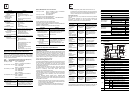
*1 Each value inside ( ) indicates the number of occupied points.
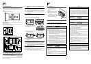
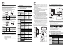
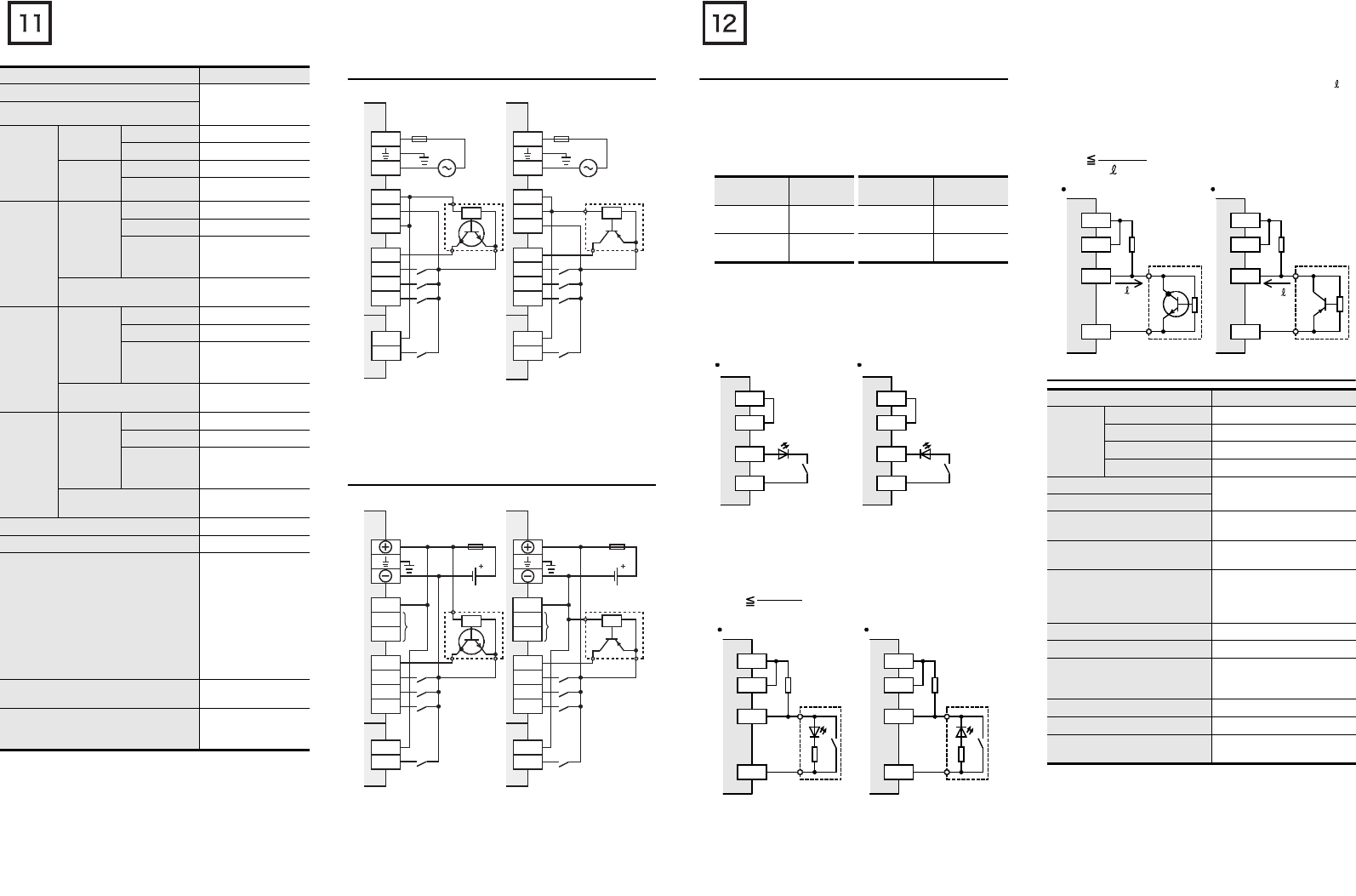
3.4.2 Examples of 24V DC input wiring[AC power type]
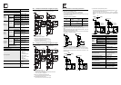
3.4.3 Examples of 24V DC input wiring[DC power type]
Input connecting type Refer to FX3U Series
User's Manual -
Hardware Edition
Input form
Input
signal
voltage
Main units
AC power Type 24V DC +10%, -10%
DC power Type
24V DC +20%, -30%
Input/output
extension
unit
AC power Type 24V DC +10%, -10%
DC power Type
24V DC +20%, -30%
Input
impedance
Main units
X000 to X005 3.9kΩ
X006, X007 3.3kΩ
X010 or more
4.3kΩ
(Does not apply to
FX3U-16M
.)
Input/output
extension unit/block
4.3kΩ
Input
signal
current
Main units
X000 to X005 6mA/24V DC
X006, X007 7mA/24V DC
X010 or more
5mA/24V DC
(Does not apply to
FX3U-16M.)
Input/output
extension unit/block
5mA/24V DC
ON input
sensitivity
current
Main units
X000 to X005 3.5mA or more
X006, X007 4.5mA or more
X010 or more
3.5mA or more
(Does not apply to
FX3U-16M
.)
Input/output
extension unit/block
3.5mA or more/24V DC
OFF input sensitivity current 1.5mA or less
Input response time Approx. 10ms
Input signal form
• Sink input:
No-voltage contact
input
NPN open
collector transistor
• Source input:
No-voltage contact
input
PNP open
collector transistor
Input circuit insulation
Photocoupler
insulation
Input operation display
LED on panel lights
when photocoupler is
driven.
Item Specification
L
N
S/S
0V
24V
X000
X001
X002
X003
L
N
S/S
0V
24V
X000
X001
X002
X003
1. Sink input type 2. Source input type
S/S
X000
S/S
X000
*
100 to 240V AC
Fuse
3-wire type
sensor
*
100 to 240V AC
Fuse
3-wire type
sensor
*Class D grounding
See section 3.3 for details.
[1] [1]
[2] [2]
[1]:Main unit, Input/output extension unit
(Common to both sink and source inputs)
[2]:Input/output extension block
(Common to both sink and source inputs)
X000
X001
X002
X003
3-wire type
sensor
*1
Fuse
*1 Class D grounding
See section 3.3 for details.
S/S
X000
X001
X002
X003
3-wire type
sensor
1.Sink input type 2.Source input type
S/S
X000
S/S
X000
[1] [1]
[2] [2]
[2]:Input/output extension block
(Common to both sink and source inputs)
[1]:Main unit, Input/output extension unit
(Common to both sink and source inputs)
S/S
*2
*2
*1
Fuse
*2
24V DC24V DC
Do not connect the (0V), (24V) terminals with others,
since they are not available.
(0V)
(24V)
(0V)
(24V)
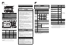
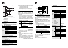
3.4.4 Instructions for connecting input devices
1) In the case of no-voltage contact:
The input current of this PLC is 5 to 7 mA/24V DC.
Use input devices applicable to this minute current.
If no-voltage contacts (switches) for large current are used,
contact failure may occur.
<Example> Products of OMRON
2) In the case of input device with built-in series diode:
The voltage drop of the series diode should be approx. 4 V or
less.
When lead switches with a series LED are used, up to two
switches can be connected in series.
Also make sure that the input current is over the input-sensing
level while the switches are ON.
3) In the case of input device with built-in parallel resistance:
Use a device having a parallel resistance, Rp, of 15 kΩ or more.
When the resistance is less than 15 kΩ, connect a bleeder
resistance, Rb, obtained from the formula as shown in the
following figure.
4) In the case of 2-wire proximity switch:
Use a two-wire proximity switch whose leakage current, , is
1.5 mA or less when the switch is off.
When the current is 1.5 mA or more, connect a bleeder
resistance, Rb, obtained from formula as shown in the following
figure.
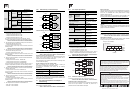
3.4.5 Input specifications (100V AC input type)
Type
Model
name
Type Model name
Microswitch
Models Z, V
and D2RV
Operation
switch
Model A3P
Proximity
switch
Model TL
Photoelectric
switch
Model E3S
X
0V
LED
24V
S/S
Sink input
X
24V
LED
0V
S/S
Source input
X
24V
0V
S/S
Source input
Rp
Rb
X
0V
24V
S/S
Rp
Rb
Sink input
15 k
Ω
or more
15 k
Ω
or more
Rb
4Rp
15-Rp
(k
Ω
)
Item Specification
Number of
input
points
FX
2N
-8EX-UA1/UL
8 points
FX
3U
-32MR/UA1
16 points
FX
2N
-48ER-UA1/UL
24 points
FX
3U
-64MR/UA1
32 points
Input connecting type
Refer to FX3U Series User's
Manual - Hardware Edition
Input form
Input signal voltage
100V AC to 120V
+10%, -15% 50/60Hz
Input impedance
Approx. 21kΩ/50Hz
Approx. 18kΩ/60Hz
Input signal current
4.7mA/100V AC 50Hz
6.2mA/110V AC 60Hz
(70% or less when turned on
simultaneously)
ON input sensitivity current
3.8mA or more
OFF input sensitivity current 1.7mA or less
Input response time
Approx. 25ms to 30ms
(A high speed receiving is
improper)
Input signal form Contact input
Input circuit insulation Photocoupler insulation
Input operation display
LED on panel lights when
photocoupler is driven.
I
X
24V
0V
S/S
Source input
Rb
X
0V
24V
S/S
Rb
Sink input
2-wire
proximity
sensor
2-wire
proximity
sensor
I
I
Rb
6
I
-1.5
(k
Ω
)