


Special offers from our partners!

Find Replacement BBQ Parts for 20,308 Models. Repair your BBQ today.

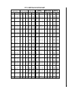
NOTE: DIAGRAMS & ILLUSTRATIONS NOT TO SCALE.
9
Figure 20
Figure 21
Figure 22
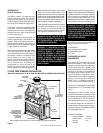
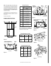
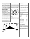
The outer chimney section installs the opposite
way; the lanced end goes down and each new
section installs OVER the outside of the previ-
ous section (
Figure 23
).
Figure 23
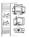
Continue to assemble the chimney up through
framed opening. Assemble just enough to pen-
etrate the roof flashing openings (
Figure 24
).
Always maintain 2" minimum air space to com-
bustible materials and always check each chim-
ney joint (inner and outer) to ensure proper
engagement. Check vertical alignment of chim-
ney so that it projects from the roof in true
vertical position.
Figure 24
Security's chimney sections do not need to be
screwed together. Additional reinforcement is
not necessary except in certain offset condi-
tions (refer to page 12,
Figure 35
).
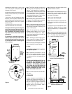
Step 4. The height of vertical chimney pipe
supported only by the fireplace must not ex-
ceed 30'. Chimney heights above 30' must be
supported by a Model FTF10-S4 stabilizer in-
stalled at 30' intervals.
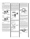
Note: The Model FTF10-S4 adds 3" net effective
height to the total chimney system.
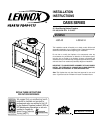
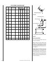
F10FS30-2
Firestop Spacer
FTF10-S4
Stabilizer
2" (51mm)
Min. Air
Space
30° Firestop
and Space Above
10' (3m) Max.
2" (51mm)
Min. Air
Space
F10FS30-2
Firestop Spacer
30° Firestop and
Space Above
10' (3m) Max.
2" (51mm)
Min. Air
Space
2" (51mm)
Min. Air
Space
FTF10-S4
Stabilizer
Locking Tabs
(Lances)
2" (51mm) Min.
Air Space to Combustibles
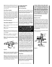
Step 3.
Note: All chimney sections are con-
structed with a unique locking tabs and hem
design, which ensures and immediate, tight
assembly between sections. Plan your chimney
requirements carefully before assembly, as the
chimney is difficult to disassemble after instal-
lation. If disassembled, the tabs might become
damaged. Be certain that the tabs are properly
formed to ensure they engage properly.
Note: For Canadian installations, all chimney
installed outside the building must be constructed
with galvalume (outer sections only) effective
January 1, 1992. The appropriate model desig-
nations are located in the back of this manual.
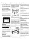
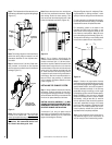
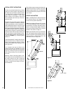
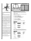
Install the Model FTF10-S4 stabilizer by fitting
inner section down into respective section of
proceeding flue pipe and locking outer stabi-
lizer section into place over the outer chimney
pipe. Position for proper clearance through
framed opening and nail straps securely (under
tension in “shear”) into place on framing. Use
8d nails. Attach successive lengths of chimney
pipe directly to stabilizer using same tech-
niques as described in Step 3 (
Figure 25
).
Figure 25
FTF8-S4 Stabilizer
Note: Assemble one component of chimney at a
time (inner section first; then outer section last)
before preceding with the next complete section.
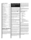
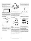
The FTF10 chimney system is a two piece chim-
ney that snap locks together from the fireplace
up. Always start with the inner flue section. With
the lanced end up, snap lock the joint into the
matching collar on top of the fireplace. At all
subsequent joints, the upper flue section fits into
the lower or preceding flue section. Each section
snaps together by means of locking tabs (9 tabs
per joint). Check each section by pulling up
slightly from the top to ensure proper engage-
ment before installing succeeding sections. If
the flue has been installed correctly, it will not
separate when tested. Also, the inner flue joint
where each section is joined should be tight and
flat without gaps (
Figure 22
).
CHIMNEY 30° OFFSET THROUGH FLOOR
OR CEILING
It may be necessary to assemble the chimney at
30° when passing through the floor or ceiling
area. Use the F10FS30-2 firestop spacer as
shown in
Figures 20 and 21
. Support the
chimney at floor or ceiling penetration with a
FTF10 stabilizer if distance of chimney below
ceiling is 10' or more. Maintain 2" minimum air
space to combustibles from chimney sections.