


Special offers from our partners!

Find Replacement BBQ Parts for 20,308 Models. Repair your BBQ today.

NOTE: DIAGRAMS & ILLUSTRATIONS NOT TO SCALE.
15
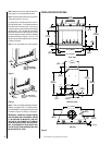
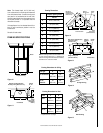
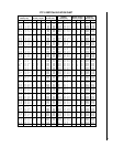
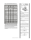
Note: See Framing and Dimension Chart for the
sizes of the ceiling and roof openings. The size
of the roof opening varies with the degree of
pitch of the roof.
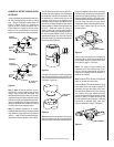
Offset Elbow Assembly
Offset elbows install the same as chimney
sections. First, snap the inner section INTO the
preceding inner section of flue. Check connec-
tion by pulling up slightly to ensure a tight fit.
Next, the outer sections snap lock OVER the
preceding outer section of chimney. Again,
check outer section by pulling up slightly to
ensure proper connection is made.
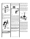
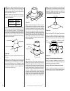
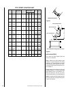
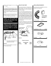
Return Elbow Assembly
Return elbows install the same way as round
terminations and stabilizers:
Step 1. Hold return elbow over top of last
chimney section.
Step 2. Center inner slip section into inner flue
pipe-slip down.
Step 3. Center outer-locking section over outer
chimney pipe. Push down until locking joint has
firmly engaged.
Step 4. Pull up slightly on return elbow to
ensure locking joint has firmly engaged.
Step 5. Secure support straps to framing
members by nailing under tension in sheer
(
Figure 38
).
Return
Elbow
Figure 38
OPTIONAL EQUIPMENT
CONSIDERATIONS
Gas Line Connection
Always plumb gas line installation per local
codes. Check all connections with soap suds;
leaks will bubble. Never test any gas line con-
nection with a match or open flame.
This provision is intended for connection to a
decorative gas appliance incorporating an au-
tomatic shut-off device and complying with the
Standard for Decorative Gas Appliances for
installation in vented fireplaces, ANSI Z21.60
(1991) or American Gas Association draft re-
quirements for Gas-Fired Log Lighters for Wood
Burning Fireplaces, Draft No. 4 dated August,
1993. Install in accordance with the National
Fuel Gas Code, ANSI Z223.1. This complies
with the revised U.L. 127 standard.
CAUTION: CERTAIN GLASS DOORS OVER-
LAP THE BLACK METAL FACING OF THE FIRE-
PLACE. IF THE FIREPLACE HAS BEEN FACED
WITH NONCOMBUSTIBLE MATERIALS,
THERE MIGHT NOT BE SUFFICIENT CLEAR-
ANCE TO INSTALL THE GLASS DOORS OF
YOUR CHOICE. ENSURE ADEQUATE CLEAR-
ANCE IS MAINTAINED AT ALL TIMES SO AS
NOT TO INTERFERE WITH THE INSTALLA-
TION AND OPERATION OF GLASS DOORS.
WARNING: THIS FIREPLACE HAS NOT BEEN
TESTED WITH AN UNVENTED GAS LOG
SET. TO REDUCE THE RISK OF FIRE OR
INJURY, DO NOT INSTALL AN UNVENTED
GAS LOG SET INTO THIS FIREPLACE.
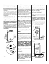
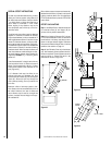
If you’re installing a gas line, connect it before
the fireplace is framed and enclosed in the
finished wall. The gas knockout is determined
by the indentation located at the bottom and
slightly off center in the side refractories. THE
KNOCKOUT IS ALWAYS REMOVED FROM IN-
SIDE THE FIREPLACE. DO NOT REMOVE THE
KNOCKOUT UNLESS YOU ARE INSTALLING A
GAS LINE. If removal is attempted from the
outer wrapper, side refractory damage may
occur. With a medium-sized hammer, lightly
tap the surface of the indentation. The refrac-
tory material is very thin in this area and is easily
removed. Once a small hole has been made,
continue tapping until you have reached suffi-
cient diameter for the gas line to fit through. The
entire knockout does not have to be removed.
Remove insulation in the gas line channel.
IMPORTANT: REPACK INSULATION MATERIAL
IN SQUARE HOLE AROUND GAS LINE, INTE-
RIOR AND EXTERIOR OF FIREPLACE, TO SEAL.
Glass Doors
If glass doors are to be installed on these
fireplaces, refer to specific installation instruc-
tions packed with the glass doors. Use only the
doors that are listed for use with these fire-
places. Use of other non-listed glass door on
these fireplaces may constitute a potential fire
hazard and is not recommended.
Note: The return elbow assembly performs
the same function as a stabilizer. Consider this
when determining the need for a stabilizer.
Note: Do not apply excessive pressure to any
subsequent chimney section following return
elbow assembly when installing. Ensure that
each subsequent chimney section is securely
attached by testing as noted above.
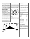
FIREPLACE FINISHES
Mantels and Trim
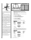
In Canada, the minimum height for a combus-
tible mantel is 18" (457 mm) above the fireplace
opening.
Figure 39
shows typical Canadian
installations. For installations other than Canada,
combustible mantels and trim may either project
in front or be flush with the finished wall as per
NFPA 211 section 7-2.3.3. and
Figure 40
. If a
mantel is of a noncombustible material, it is
exempt from these requirements as long as it
does not interfere with the installation or opera-
tion of glass doors.
Note: Do not place any combustible materials
on the fireplace face.
Figure 39
Finished
Wall
Header
8" Max.
(203mm)
Noncombustible
Wall Covering
Fireplace Opening
Canadian Installation
18" Min.
(457mm)
Combustible
Mantel
Spacer