


Special offers from our partners!

Find Replacement BBQ Parts for 20,308 Models. Repair your BBQ today.

NOTE: DIAGRAMS & ILLUSTRATIONS NOT TO SCALE.
6
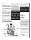
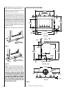
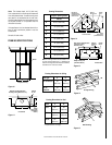
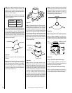
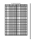
FIREPLACE SPECIFICATIONS
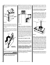
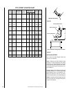
Figure 9
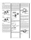
Step 3. Refer to fireplace drawings and speci-
fications on pages 6 and 7 for framing dimen-
sions and details. Frame appliance enclosure as
illustrated in
Figures 10 through 13
on page 7.
IMPORTANT: UNDER NO CIRCUMSTANCES
CAN THE FIREPLACE TOP SPACERS (
FIGURE
9
) BE REMOVED OR MODIFIED, NOR MAY
YOU NOTCH THE HEADER TO FIT AROUND
OR BE INSTALLED LOWER THAN THE SPAC-
ERS. THE HEADER MAY BE IN DIRECT CON-
TACT WITH THE TOP SPACERS BUT MAY NOT
BE SUPPORTED BY THEM.
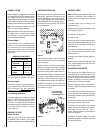
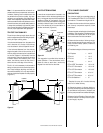
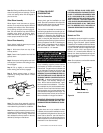
Figure 8
Figure 7
11"
(279mm)
49 ⁵⁄₈"
(1260mm)
31" (788mm)
9 ³⁄₄"
(248mm)
¹⁄₂" (13mm)
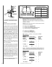
Front View
51 ¹⁄₈"
(1299mm)
6 ¹⁵⁄₁₆"
(176mm)
1 ⁹⁄₁₆"
(40mm)
¹⁄₂"
(13mm)
42 ³⁄₄" (1086mm)
24 ¹⁄₁₆"
(611mm)
4 ³⁄₁₆"
(106mm)
¹⁄₂"
(13mm)
25 ¹⁄₈"
(638mm)
5 ¹⁄₁₆"
(129mm)
11 ⁵⁄₁₆"
(287mm)
8 ⁵⁄₈"
(219mm)
52 ¹⁄₄" (1327mm)
39 ¹¹⁄₁₆"
(1008mm)
4 ¹⁄₂"
114mm)
Side View (Left)
Top View
44 ⁵⁄₈"
(1133mm)
12 ⁷⁄₁₆"
(316mm)
39 ¹¹⁄₁₆"
(1008mm)
9 ¹⁵⁄₁₆"
(252mm)
1
⁹⁄₁₆
"
(40mm)
1 ¹⁄₄"
(32mm)
Drain
Plug
11 ⁵⁄₁₆"
(287mm)
Metal Safety Strips
with ¹⁄₂" (13mm) Min.
Overlap
1 ¹⁄₂"
(38mm)
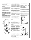
The safety strips should extend from front of
the fireplace at least 1 ¹⁄₂" and should extend to
be at least flush with the sides. In the event a
wooden support is used to elevate the fireplace
above the floor, a “Z” type safety strip should be
fabricated and used to protect the front surface
of the wood support as well as the floor beneath
the hearth extension (
Figures 7 and 8
). The
safety strips should be tacked down to prevent
possible movement.
Note: The “Z” type safety strip is not supplied.
Special “Z” Metal Safety
Strips with ¹⁄₂" (13mm) Min.
Overlap
2"
(51mm)
Blocking
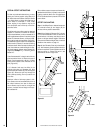
Note: Safety strips are not required when fire-
place rests on a noncombustible surface.
Note: Install the hearth extension only as illus-
trated (see Figures 41 and 42 ).