


Special offers from our partners!

Find Replacement BBQ Parts for 20,308 Models. Repair your BBQ today.

NOTE: DIAGRAMS & ILLUSTRATIONS NOT TO SCALE.
5
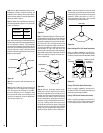
Figure 6
Figure 5
INSTALLING THE FIREPLACE
Step 1. Slide the fireplace into prepared fram-
ing or position fireplace in its final position and
frame later.
The fireplace may not be recessed into a com-
bustible floor. Maintain the floor to hearth
clearance established by the fireplace lower
front face.
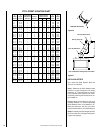
Step 2. Insert the provided metal safety strips,
beneath the fireplace as illustrated (
Figures 5, 6
and 7
). The safety strips should overlap ¹⁄₂"
min. for continual coverage of the floor.
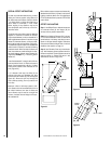
Air Inlet
The installation of the air inlet is required for
safe fireplace operation.
Step 1. Determine the location for air inlet,
which can be installed through an outside
wall. A 6 1/2" diameter hole will be required
for installation of the air inlet assembly (
see
Figure 17
).
CAUTION: AVOID INSTALLING THE AIR IN-
LET WHERE THE OPENING COULD BE
BLOCKED BY SNOW, BUSHES OR OTHER
OBSTACLES. THE MAXIMUM HEIGHT FOR
THE OUTSIDE AIR IS 50 FEET ABOVE THE
HEARTH, PROVIDING THE AIR INLET IS TER-
MINATED A MINIMUM OF THREE (3) FEET
BELOW THE CHIMNEY CAP LEVEL.
Note: Air inlet ducts must not terminate in
attic space.
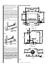
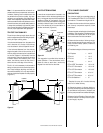
CLEARANCES
Minimum clearance to combustibles for the
fireplace is as follows; sides and back – ¹⁄₂"
(13mm), combustible floor – 0" (0mm), adja-
cent wall 18" (457mm), adjacent shielded wall
(
K factor of .84 or less 40" W x 40" H
) 12"
(305mm), ceiling – 37 ¹⁄₂" (953mm).
Refer to
page 17 for more detail
.
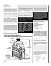
Figure 4
Metal Safety Strip
Floor
Hearth
Extension
¹⁄₂" (13mm)
Maintain
¹⁄₂" (13mm)
Air Space
at Sides
and Back
Combustible
Wall
Fireplace On Non-Combustible Floor
Metal Safety Strip
Floor
¹⁄₂" (13mm)
Maintain
¹⁄₂" (13mm)
Air Space
at Sides
and Back
Combustible
Wall
Platform
Hearth
Extension
Fireplace On Combustible Floor
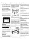
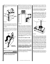
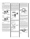
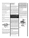
Drain Connector
(see Detail A )
Seal All
Seams,
Joints
And
Corners
Around The
Bottom Of
Fireplace
Access
Drain Plug
Through
Air Inlet
Opening
Detail A
Threaded
Reducer
³⁄₄” x ¹⁄₂”
(PVC)
Threaded
Elbow ³⁄₄”
@ 90°
(PVC)
Step 2. Locate the drainage plug and remove
it by depressing the locking tabs and pushing
down through the outside air opening at the
bottom of the fireplace.
Step 3. On the exposed hole, install a PVC
threaded coupling reducer, 3/4" x 1/2" going
from inside of the fireplace out. Apply a
silicone-based sealant around the base and
threads before installation.
Step 4. Holding the reducer coupling with a
wrench, thread a 3/4", 90 degree, PVC elbow to
the reducer until it is tight to the metal.
Note: To assure proper drainage, the fireplace
must be installed on a leveled surface.
Note: Clearance at the nailing flange for both
fireplace models is 0" (0mm).
Note: Adjacent wall considerations are for an
adjacent wall on only a single side. Walls
should not be placed at minimum distance at
both sides of the fireplace.
Note: The LSO-43 has been provided with a
drain plug under the fireplace by the air inlet
opening. If the fireplace is on a platform or
wooden surface, a hole must be bored to make
room for an elbow connector. If the fireplace is
on a concrete floor, it will be necessary to
elevate the appliance at least 1" high to permit
the installation of an elbow connector.
Step 1. Seal all joints, gaps and corners around
the bottom of the fireplace before positioning
the fireplace on its location (
Figure 4
).
3. Note the floor construction, i.e. 2 x 6’s, 2 x 8’s
or 2 x 10’s, single or double joists, type and
thickness of floor boards.
4. Use this information and consult your local
building code to determine if you need addi-
tional support.
If you plan to raise the fireplace and hearth
extension, build the platform assembly then
position fireplace and hearth extension on top.
Secure the platform to the floor to prevent
possible shifting.
WATERPROOFING THE FIREPLACE
Although the LSO-43 fireplace is designed to
drain to the front most of the water from rain
and other sources that may enter the hearth
area, condensation and unusual conditions
may cause water to collect inside the fire-
place bottom.
To prevent this, the builder must provide a
means to drain water from under the fire-
place by building or installing a water collec-
tor of the builder's choice, or installing a PVC
drain as follows: