


Special offers from our partners!

Find Replacement BBQ Parts for 20,308 Models. Repair your BBQ today.

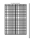
NOTE: DIAGRAMS & ILLUSTRATIONS NOT TO SCALE.
8
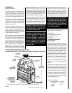
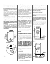
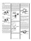
Step 4. The fireplace should be secured to the
side framing members through the nailing flange
(
Figure 16
).
Figure 16
Note: The nailing flange and the area directly
behind the nailing flange is exempt from the
clearances described on the fireplace clear-
ance label.
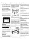
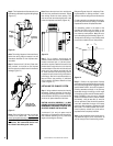
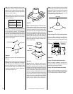
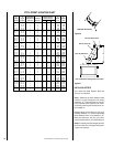
Step 5. Connect the 6" (152 mm) Class 0 air
duct provided, to the collar on the fireplace
with the clamps provided in the kit’s hardware
package (
Figure 17
).
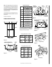
Step 2. Position the appropriate firestop
spacer at the ceiling and fasten temporarily with
two (2) 8d nails or equivalent. Use a flat firestop
spacer, Model F10FS-2, for the FTF10 system if
chimney penetrates vertically. If the chimney
penetrates through the ceiling at a 30° angle
(offset chimney) then use a 30° firestop spacer,
Model F10FS30-2. Use one nail on opposite
sides of the firestop to hold in position. Fasten
permanently, using at least two (2) more 8d
nails or equivalent, after the chimney sections
have been assembled through the firestop
spacer and after necessary adjustments have
been made. The firestop spacer must be se-
cured in place by at least four (4) 8d nails or
equivalent when completely installed.
Note: If patio installation requires that a chim-
ney passes through a roof or room above, be
sure to comply with all local building codes.
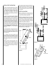
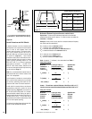
Figure 19
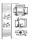
Reference
Figures 14 and 15
and charts “Fram-
ing Dimensions for Ceiling and Roof,” which
specify minimum ceiling and roof dimensions.
For new construction, to determine chimney cen-
ter line, use plumb line from ceiling or roof above
fireplace to the center of fireplace flue collar.
For remodeling, plumb to the center of the
fireplace flue collar from the ceiling or roof
above. Drive a nail through the ceiling or roof
from below to mark position. Mark and cut a
hole in the ceiling (around the nail) (
Figure 19
).
Then plumb from ceiling or roof directly above
the cut hole to determine roof hole position.
Step 6. Route the Class 0 air duct out the back
or side to an outside wall.
The duct inlet
should be located above any anticipated snow
level. Check local building codes for any
restrictions. We recommend that the inlet
be at least 4 feet above grade level.
Step 7. Cut or frame a hole through the
outside of the enclosure for the installation of
the duct inlet hood. A 6 ¹⁄₂" (165 mm) diam-
eter hole is required. Feed the loose end of the
flexible duct through the hole cut for the inlet
hood and attach to the collar on the inlet hood
using one of two clalmps provided with the
kit. Insert the hood into the opening. Secure
in place with nails driven through the holes in
hood flange. Seal with noncombustible wa-
terproof silicon type caulking. If additional
duct is needed, use Class 0 metallic air duct
(
refer to Figure 17
).
INSTALLING THE CHIMNEY SYSTEM
Step 1. Using standard construction framing
techniques, construct openings for the chim-
ney through the ceiling(s) and roof or through
an outside chase. All framing must maintain the
minimum air space clearance at all times.
CAUTION: ALLOW A MINIMUM 2" (51 MM)
CHIMNEY AIR SPACE TO COMBUSTIBLE FRAM-
ING MEMBERS THROUGHOUT VERTICAL AND/
OR OFFSET CHIMNEY INSTALLATIONS.
A minimum 2" (51 mm) air space must be
reserved for all combustible and noncombus-
tible materials extending for any continuous
length surrounding the chimney.
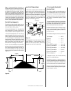
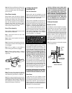
Figure 18
Figure 17
Air Duct
Air Inlet
Clamps
Note: Air Inlet
Must Be Free Of
Any Obstructions
3 Feet
Note: Secure the duct hood to a vertical post
with the inlet positioned downward. Ensure
that nothing blocks the hood opening. This
duct must never terminate higher than 3 feet
below the fireplace termination (Figure 18 ).
8d Nail Or
Equivalent
Framing
Stud
Nailing
Flange