


Special offers from our partners!

Find Replacement BBQ Parts for 20,308 Models. Repair your BBQ today.

3
CONGRATULATIONS ON THE PURCHASE OF YOUR NEW
GAS APPLIANCE MANUFACTURED BY LENNOX HEARTH
PRODUCTS.
When you purchased your new gas-fired heater, you joined the ranks
of thousands of individuals whose answer to their home heating needs
reflects their concern for efficiency and our environment. We extend our
continued support to help you achieve the maximum benefit and enjoy
-
ment available from your new gas-fired heater. It is our goal at Lennox
Hearth Products to provide you, our valued customer, with an appliance
that will ensure years of trouble-free warmth and pleasure.
Thank you for selecting a Lennox Hearth Products gas-fired heater as
the answer to your home heating needs.
Sincerely, All of us at Lennox Hearth Products
TABLE OF CONTENTS
Important Safety and Warning Information ..................... Page 2
Packaging List ..............................................................
Page 3
Introduction ................................................................. Page 3
General Information .....................................................
Page 4
Codes and Approvals ...................................................
Page 4
New York City MEA Approval .......................................
Page 6
Requirements for the
Commonwealth of Massachusetts ..........................
Page 6
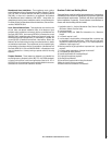
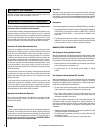
Specifications - Insert Dimensions ..............................
Page 7
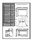
Clearances to Combustibles .........................................
Page 8
Installation ................................................................... Page 9
Fireplace Requirements
........................................... Page 9
Venting Requirements .............................................
Page 10-11
Insert Leveling ........................................................
Page 11
Door Assembly Installation
or Removal Instructions
...................................... Page 12
Refractory Brick Panel Installation Instructions ......
Page 13
Log Set Installation Instructions .............................
Page 14-15
Surround Installation Instructions ..........................
Page 16
Gas Line Installation .....................................................
Page 18
Gas Pressure Requirements
.................................... Page 18
LP and Natural Gas Supplies ...................................
Page 18
Operating Instructions .................................................
Page 18-22
Pre-Lighting Checklist .............................................
Page 18
Lighting Instructions ...............................................
Page 19
To Turn Gas Off to Appliance ...................................
Page 19
Shutdown Procedure ..............................................
Page 19
Flame Appearance and Sooting ...............................
Page 20
Air Shutter Adjustment ...........................................
Page 20
Burn-In Period ........................................................
Page 21
Quiet Operation .......................................................
Page 21
Blower Operation and Wiring Diagram ....................
Page 21
Shoreline™ Main Burner Operation .........................
Page 22
Millivolt Control System and Wiring Diagram .........
Page 22
Maintenance and Servicing ..........................................
Page 23-25
Maintenance Checklist ............................................
Page 23
Glass Maintenance ..................................................
Page 23-24
Door Removal .........................................................
Page 24
Blower Removal ......................................................
Page 24
Paint Touch-Up .......................................................
Page 24
Inspecting Wiring ....................................................
Page 24
Fuel Conversion Kits ...............................................
Page 24
Maintenance Schedule ............................................
Page 25
Troubleshooting ........................................................... Page 26
Replacement Parts List. ...............................................
Page 27
Part Identification .........................................................
Page 28-32
Optional Accessories ....................................................
Page 33-35
Safety / Listing Label ....................................................
Page 36
Lighting Instructions Label ..........................................
Page 37
Warranty and Product Reference Information ..............
Page 38
PACKAGING LIST
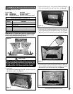
To install a Shoreline insert, an insert body, refractory brick panel set
and surround kit are required (each sold separately. See
Page 34 for
ordering information).
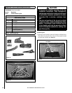
Fireplace Insert Body Packaging List
Model: Shoreline 33/40 DV INS
1) Fireplace Insert Body ......................1) 150 cfm Blower
with Burner Cassette
......................1) 5-Piece Log Set
1) Gas pipe (3/8” x 8”)
........................1) Optional Shoreline #33 orifice
1) Installation and Operation Manual
..1) Bag of Decorative Lava Rock
1) Bag of Glowing Ember Material
......1) Fireplace Warning Label
1) Front Leveling Leg Kit
Refractory Brick Panel Sets - 6 pieces:
Standard
Red
Architectural Stone
Surround Kits:
Small 3-sided - 36-5/8” Wide x 25-7/8” High (930 mm x 657 mm)
Large 3-sided - 41” Wide x 28” High (1041 mm x 711 mm)
Small 4-sided - 36-5/8” Wide x 29-3/16” High (930 mm x 741 mm)
Large 4-sided - 41” Wide x 33-1/2” High (1041 mm x 851 mm)
This installation manual will help you obtain a safe, efficient, depend-
able installation for your appliance and vent system.
PLEASE READ AND UNDERSTAND THESE INSTRUCTIONS
BEFORE BEGINNING YOUR INSTALLATION
INTRODUCTION
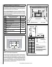
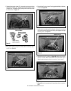
The Insert models covered in this manual are direct-vent sealed com-
bustion gas heaters designed for residential application for installation
into an existing masonry or factory built solid fuel burning fireplace. The
required liners for the air intake and exhaust are as follows:
•
Air Intake: Use 3” diameter UL 181 or UL 1777 listed liner only.
• Exhaust: Use 3” diameter UL 1777 listed gas vent liner only. DO
NOT USE UL 181 LISTED LINER.
These vent systems must be routed through the existing fireplace flue
system to the vent termination.
Installation Options
• .Residential • Manufactured (mobile) home
• .Bedrooms • Commercial
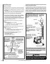
Your direct vent Insert is designed to be vented vertically with a minimum
height of 10 feet and maximum of 35 feet from top of the flue collar using
natural gas or propane gas (LP).
This appliance is only for use with the type of gas indicated on the
rating plate. This appliance is not convertible for use with other gases,
unless a certified kit is used.
Cet appareil doit être utilisé uniquement avec les types de gaz indiqués
sur la plaque signalétique. Ne pas l'utiliser avec d'autres gaz sauf si
un kit de conversion certifié est installé.
These appliances comply with National Safety Standards and are tested
and listed by OMNI-Test Laboratories Inc.; Beaverton, Oregon (Report No.
050-F-22-5) to ANSI Z21.88-2005/CSA 2.33-2005, and CGA 2.17-M91 in
both USA and Canada, as Vented Gas Fireplace Heaters and are approved
for installation in bedrooms and manufactured (mobile) homes.