


Special offers from our partners!

Find Replacement BBQ Parts for 20,308 Models. Repair your BBQ today.
11
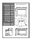
NOTE: DIAGRAMS AND ILLUSTRATIONS ARE NOT TO SCALE
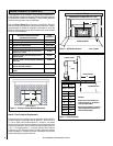
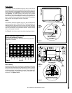
Vertical Venting
The vent pipes must be connected to the proper collars on the unit and
the exhaust vent pipe must be connected to the termination cap or the
unit will not operate. The combustion air vent pipe can be connected to
the termination cap (see
Figure 6b) or it can terminate inside the chimney
(see
Figure 6a). The bottom opening of the chimney must be sealed
around the vent pipes if the combustion air vent is not connected to the
termination cap. Use unfaced fiberglass insulation to seal around the vent
pipes or a positive flue connection using a seal-off plate. The insulation
may give off an odor during the first hour of operation.
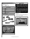
NOTES:
The minimum vertical rise (exhaust vent) is 10 feet (3.05 M) and the
maximum vertical rise is 35 feet (10.67 M). These dimensions are
measured from the flue collar of the unit to the end of the vent pipe,
The fireplace and fireplace chimney must be clean and in good working
order and constructed of non-combustible materials. Inspect chimney
clean-outs for proper fit and seal.
See Table 5 for the minimum vertical termination height requirements.
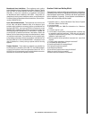
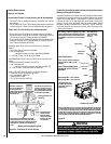
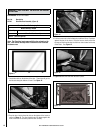
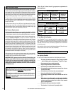
DETAIL B
Use 5/32 allen wrench to loosen
and adjust bracket up or down,
tighten when at right height
Right front leveling leg
Use open end 9/16”
wrench to adjust height
up or down
Front leveling legs
See
Detail B
Rear leveling legs
Figure 7
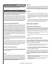
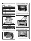
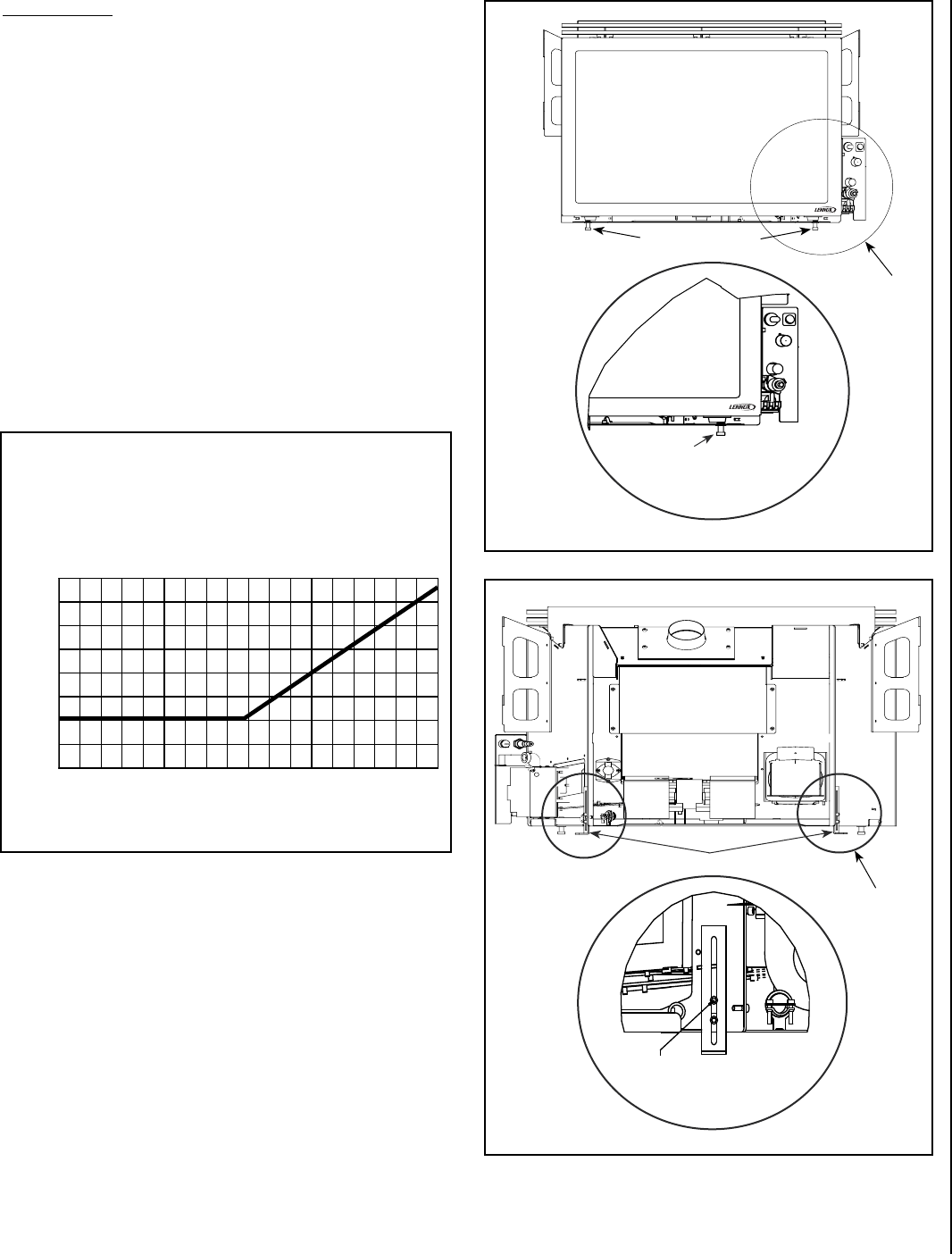
DETAIL B
See
Detail C
FRONT
LEVELING
LEGS
REAR
LEVELING
LEGS
Figure 8
DETAIL C
� � � � � � � � � � � � � � � � � �
� � � � � � � � � � � � � � � � � �
� � � � � � � � � � � � � � � � � �
� � � � � � � � � � � � � � � � � �
� � � � � � � � � � � � � � � � � �
� � � � � � � � � � � � � � � � � �
� � � � � � � � � � � � � � � � � �
� � � � � � � � � � � � � � � � � �
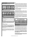
Vertical Termination Height Minimum
(Factory Built and Masonry Fireplaces)
The vent/air intake termination clearances above the high side of an
angled roof is as follows:
8 (2.4)
7 (2.1)
6 (1.8)
5 (1.5)
4 (1.2)
3 (0.9)
2 (0.6)
1 (0.3)
0 (0.0)
2/12
4/12
6/12
8/12
10/12
12/12
14/12
16/12
Table 5
Feet (meters)
Roof Pitch
Insert Leveling
At each front and rear corner of the insert is an adjustable leg provided
to level the insert should the hearth of the fireplace be uneven. To adjust
the legs in the rear, loosen the two 5/32” allen head screws, move the leg
to the desired height, and then tighten the screws. Repeat these steps
for each adjusting leg. To adjust the legs in the front use a 9/16” open
end wrench. See
Figures 7 and 8.