


Special offers from our partners!

Find Replacement BBQ Parts for 20,308 Models. Repair your BBQ today.

21
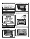
NOTE: DIAGRAMS AND ILLUSTRATIONS ARE NOT TO SCALE
Blower Operation
Your Shoreline gas insert comes equipped with a 150 CFM blower with
a variable speed control and an automatic temperature activated On/Off
snap switch.
1. Plug the blower power cord into a grounded (three-prong) outlet.
Read Warning above.
2. After the fireplace insert warms up, the blower will turn on if the speed
control (located at the right below the firebox) is left in the "ON" posi
-
tion. The blower will not operate until the fireplace insert is warm.
3. Once the blower turns on, turn the knob to the desired speed. No
further adjustment is necessary.
4. If you do not wish to have the blower on, turn the knob counterclock
-
wise until it clicks into the "OFF" position.
WARNING
The power cord must be plugged directly into a prop-
erly grounded, 120 Volt, 60 Hz, 3-prong receptacle
electrical outlet. Do not cut or remove the ground-
ing prong from this plug. It must be routed to avoid
contact. Do not route power cord under or in front
of appliance.
IMPORTANT
Keep your house well ventilated during the curing
process. The odor and haze emitted by the curing
process can be quite noticeable and may set off a
smoke detector.
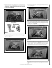
Burn-In Period
This Shoreline™ insert has been painted with a high temperature metal-
lic black stove paint. It leaves the factory dry to the touch, but finishes
curing as the fireplace insert is used. Fire the fireplace insert four suc
-
cessive times for ten minutes each time with a five minute cool down
between each firing to cure the paint and burn off lubricants used in the
manufacturing process. Ventilate the house during these first firings as
the paint gives off an unpleasant odor. It is recommended that persons
sensitive to an imbalance in the indoor air quality avoid the area where
the fireplace insert is located during the curing process.
Do not turn on
blower during Burn-In period.
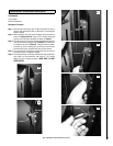
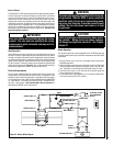
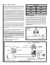
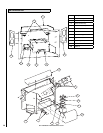
CAUTION
Label all wires prior to disconnection when servic-
ing controls. Wiring errors can cause improper
and dangerous appliance operation. See Figures
36 and 37.
Figure 36 - Blower Wiring Diagram
BLACK
MALE SPADE
1/4”
FEMALE
SPADE 1/4”
WHITE
BLOWER RHEOSTAT
BLACK
BLOWER
MALE SPADE 1-4”
FEMALE SPADE 1/4”
POWER CORD
BLACK
GREEN/GROUND
WHITE
MALE SPADE 1/4”
FEMALE SPADE 1/4”
FEMALE SPADE 1/4”
WHITE
BLACK
WHITE
BLOWER SNAP DISC
Quiet Operation
As the Shoreline is burning, a number of normal operational sounds may
be heard. The flow of gas through the gas valve and orifice may make a
rushing or whistling noise. If this noise is objectionable, it can be reduced
by turning down the flame. Turning down the flame can reduce total heat
output by more than 30%. When the blower turns on, the sound of rushing
air may be heard. The blower sounds may be reduced by adjusting the
speed control rheostat (see
Figure 31). Also, a slight clicking sound may
be heard as the gas valve or blower switch turn on and off.
Electrical Requirements
This gas insert operates without an outside power source, however the
blower requires a 120-Volt electrical service outlet. This appliance, when
installed, must be electrically grounded in accordance with local codes,
or in the absence of local codes, the National Electrical Code ANSI/NFPA
70 - latest edition. In Canada, the current CSA C22-1 Canadian Electri-
cal Code - latest edition. (
See Shoreline Main Burner Operation for
thermostat and ON/OFF switch information).
BLACK
PLUG INTO 120 VAC
60 HZ GROUNDED
OUTLET