


Special offers from our partners!

Find Replacement BBQ Parts for 20,308 Models. Repair your BBQ today.

22
NOTE: DIAGRAMS AND ILLUSTRATIONS ARE NOT TO SCALE
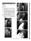
Shoreline™ Main Burner Operation
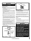
Your Shoreline fireplace insert comes with an “ON/OFF” rocker switch
used to turn the burner on and off while the pilot is on. The rocker switch
is located in the control panel above the blower rheostat switch and to the
left of the igniter. This is all located behind the right side surround.
A wall-mounted switch, a millivolt wall thermostat, or a remote control,
can be used to supplement the rocker switch. The gas valve is powered
by millivolts generated by the pilot assembly. This millivolt system is very
sensitive to electrical resistance, therefore, make sure all connections are
tight, clean, and free from corrosion. Do not splice any millivolt wires.
Consult
Table 12 to determine the proper gage of wire for the thermostat
or wall switch connections. This chart refers to the total length of the wire
(out to the switch and back). The thermostat must be a millivolt type.
A 24-volt furnace thermostat will not work. Never hook up household
current - 120 Volts - to the millivolt system. It is not recommended to
hook up any more than two switches to the fireplace insert (for example
a rocker switch and a wall thermostat). Additional switches may affect
the system resistance and increase the chance of the burner not igniting.
Follow the instructions included with the thermostat or remote control
for wiring.
The thermostat, remote control, and rocker switch will turn the burner
on and off independently. Be sure to set the rocker switch to the “OFF”
position when using the thermostat or remote control and set the ther
-
mostat or remote control to the lowest temperature when you wish to
use the rocker switch only, otherwise one may override the other. If a
remote thermostat is to be used with the insert, do not place the receiver
under the firebox.
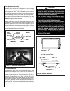
Care should be taken to ensure any installed wires from thermostat do
not come in contact with the hot surfaces of the firebox.
IMPORTANT NOTE: If a wall thermostat is to be installed, install the
thermostat per the manufacturers instructions, provided with the ther-
mostat. Failure to follow manufacturers instructions could result in a
malfunction. Pay special attention to the thermostat location require-
ments. If the location requirements are not adhered to the appliance,
erratic operation or failure may occur. Do not mount the thermostat
where it may be affected by:
• Radiant heat from the stove, fireplaces, sun or other heat
sources.
• Drafts or dead spots behind doors or in corners.
• Hot or cold air from ducts.
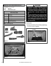
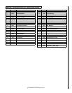
Thermostat Wire
Wire Size Maximum Length
12 Gage
100 Feet
14 Gage 64 Feet
16 Gage 40 Feet
18 Gage 25 Feet
20 Gage
16 Feet
Table 12
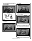
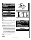
Millivolt Control System
This Shoreline fireplace insert operates on a millivolt control system.
As such, no additional power supply is needed for the Shoreline insert
to heat. The pilot assembly contains a thermocouple, that when heated
by the pilot flame, generates electricity (millivolts- mV=1/1000 of a volt)
which opens a valve allowing gas to flow to the pilot assembly. The
pilot assembly also contains a thermopile, that when heated by the pilot
flame, generates electricity that flows to terminal #1 (labeled TH/TP)
on the gas valve. When the electricity is conducted from terminal #1
through the on/off switch, thermostat, or receiver of the remote control
to terminal #3 (labeled TH) on the gas valve, the main burner will ignite.
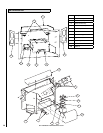
See
Figures 37 and 38.
PILOT
OFF
ON
HI
LO
PILOT
TPTH
TP TH
1
2
3
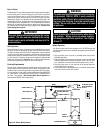
Figure 37 Millivolt Wiring Diagram
Gas Valve
Thermopile
Inlet Pressure Tap
ON/OFF Switch
(Burner)
ON/OFF switch or thermo-
stat - Connect to terminal
3 on gas valve
Pilot Hood
Igniter (sparker)
Thermocouple
Pilot Assembly
Pilot Tube
Piezo Igniter
Manifold Pressure Tap
Gas Inlet
Pilot/On/Off Gas
Control Knob
Flame Height (HI/LO)
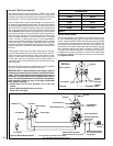
Detail A - See
Figure 38
ON/OFF switch or thermostat -
Connect to terminal 1 on gas valve
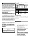
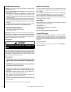
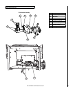
DETAIL A
PILOT
OFF
ON
HI
LO
PILOT
TPTH
TP TH
1
2
3
To optional
remote or
thermostat
To Thermopile
To ON/OFF
Switch
Figure 38
Gas Valve
Refer to Figure 37
Pilot Adjustment Screw
NOTE: DIAGRAMS AND ILLUSTRATIONS ARE NOT TO SCALE