


Special offers from our partners!

Find Replacement BBQ Parts for 20,308 Models. Repair your BBQ today.

18
NOTE: DIAGRAMS AND ILLUSTRATIONS ARE NOT TO SCALE
We recommend that a qualified individual such as a plumber or gas fitter be
used to correctly size and route the gas supply line to the appliance. Installing
a gas supply line from the fuel supply to the appliance involves numerous
considerations of materials, protection, sizing, locations, controls, pressure,
sediment, and more. Certainly no one unfamiliar and unqualified should attempt
sizing or installing gas piping. Never use galvanized or plastic pipe.
The gas supply line should be plumbed from the fuel source to the area
where the appliance is to be installed per requirements outlined in NFPA
54 - latest edition (USA) or CAN/CSA B149.1 - latest edition (Canada)
and per local codes.
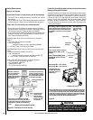
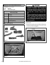
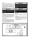
The insert comes with an 8 inch (203 mm) nipple attached to the supply
side of the gas valve. After connecting the gas line, all joints in the line
and connections at the valve should be checked for leaks using a gas
leak test solution before final positioning of the unit.
Gas Pressure Requirements
It is important to check the gas pressure during the initial installation
of the insert and ensure there are no operating problems. This insert
will not function properly unless the required gas pressure is supplied.
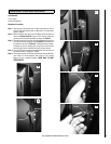
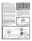
Two pressure taps are provided on the insert's valve to check gas pres
-
sures (see
Figure 37 on Page 22). The taps are located to the left of the
on/off/pilot knob. The top tap is the inlet (supply) pressure side. To check
inlet pressure (with the fireplace insert burning), insert a small regular
screwdriver into the tap and turn a half turn counterclockwise. Cover the
tap with the line from a manometer and check the pressure. Close the tap
gently but securely after completing the check. The manifold (outlet) tap
is below the inlet tap. To check manifold pressure (with the insert burning
at the high burn setting) insert a small phillips screwdriver into the tap
and turn a half turn counterclockwise. Cover the tap with the line from
the manometer and check the pressure. Again, close the tap gently but
securely after completing the check. Check the taps for gas leaks with a
gas leak test solution and retighten if necessary.
If the pressure is too low, make sure the gas supply line is large enough,
the supply regulator is properly adjusted, and the total gas load for the
residence does not exceed the amount supplied.
IMPORTANT NOTE: If propane is used, be aware that if the tank size is too
small (i.e. under 100-lbs, if this is the only gas appliance in the dwelling.
Ref. NPFA 58), there may be loss of pressure, resulting in insufficient fuel
delivery (which can result in sooting or other malfunctions). Any damage
resulting from an improper installation, such as this, is not covered under
the limited warranty.
LP and Natural Gas Supplies
Your Shoreline™ can be operated with either natural gas or liquid
propane (LP). It is shipped from the factory for use with only natural
gas. The fireplace insert must always be operated with the same gas as
specified on the label unless converted by a qualified service technician
as per this manual.
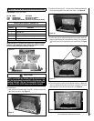
Also check the orifice size on the label located below the Shoreline insert.
It must be the correct size for the fuel and altitude.
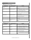
Inlet Gas Supply Pressure
Fuel # Minimum Maximum Desired
Natural
Gas
5" WC/po. C.E
(1.25 kPa)
10.5" WC/po. C.E
(2.61 kPa)
7" WC/po. C.E
(1.74 kPa)
Propane
10.5" WC/po. C.E
(2.61 kPa)
13.0" WC/po. C.E
(3.23 kPa)
11" WC/po. C.E
(2.74 kPa)
Table 10
Manifold Gas Supply Pressure
Fuel # Low High
Natural Gas
(Lo) 1.3" WC/po. C.E
(.32 kPa)
(Hi) 3.5" WC/po. C.E
(.87 kPa)
Propane
(Lo) 5.4" WC/po. C.E
(1.35 kPa)
(Hi) 10.0" WC/po. C.E
(2.49 kPa)
Table 11
These appliances and their individual shut-off valves must be discon-
nected from the gas supply piping system during any pressure testing
of that system at pressures
greater than 1/2 psig (3.5 kPa).
These appliances must be isolated from the gas supply piping system
(by closing their individual manual shut-off valve) during any pressure
testing of the gas supply piping system at test pressures equal to or
less than 1/2 psig (3.5 kPa).
Tables 10 and 11 show the units' gas pressure requirements for
these appliances.
GAS LINE INSTALLATION
Pre-Lighting Checklist
Be sure to check these items before the initial lighting of the insert:
_____ The insert gas label corresponds to the gas supply available
- that is "natural gas" for natural gas or "LP gas" for LP gas.
_____ Gas pressure has been checked carefully.
_____ All gas fittings have been checked for leaks.
_____ All clearances to combustibles have been met.
_____ All combustible materials have been removed from the area
in front of the insert.
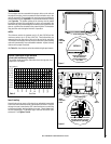
_____ All vented areas of the insert face are unobstructed.
_____ House is ventilated to clear initial curing odor.
_____ All packaging materials have been removed from the fire
-
box.
_____ While insert is cool, fingerprints or other marks should be
cleaned from any surfaces with a soft cloth. Marks left on these
surfaces may become etched into the finish if not removed
prior to burning the unit.
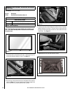
_____ Brick panels and log set have been installed.
_____ The glass door is in place and is properly sealed.
OPERATING INSTRUCTIONS