


Special offers from our partners!

Find Replacement BBQ Parts for 20,308 Models. Repair your BBQ today.

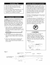
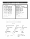
The following table illustrates a breakdown of the hardware pack. It highlights what components are used
in the various stages of assembly.
Ref.
P55F5A
P5540B
H025
P55M3A
Component Qty. to Use
Customized Wrench 1
Manual Lighting Stick 1
M4x8mm Pattern Head Screw 1
Tightening Tool 1
Actual Size and Quantity of
Customized Wrench
Qty. 1
Ref. # P55F5A
Scale 1:0.6
Purpose of Components
Tighten Caster
Attaches To Outside Bowl Panel - Left
Attaches To Outside Bowl Panel - Left
Allows you to tighten Pattern Head Thumb Screws
as needed
Each Hardware Piece:
X_
Tightening Tool M4x8mm Pattern Head Screw
Qty. 1 Qty. 1
Ref. # P55M3A Ref. # H025
Manual Lighting Stick
Qty. 1 Ref. # P5540B
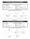
Ref.
P3430A
P55L7A
H025
H027
Component Qty. to Use
Control Knob 1
Cotter Pin 1
M4x8mm Pattern Head Screw 2
M4 Plain Washer 2
Purpose of Components
Install To Side Burner Valve Stem
Secure To Side burner
Attaches To Side Burner Valve Bracket
Attaches To Side Burner Valve Bracket
Actual Size and Quantity of Each Hardware Piece:
s
I
_. M4x8mm Pattern Head Screw
Qty. 2
Ref. # H025
Control Knob Cotter Pin
Qty. 1 Qty. 1
Ref. # P3430A Ref. # P55L7A
©
M4 Plain Washer
Qty. 2
Ref. # H027