


Special offers from our partners!

Find Replacement BBQ Parts for 20,308 Models. Repair your BBQ today.
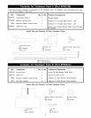
Install the Door Bracket to the inside of front
Cart Legs. Align the threaded holes on the Door
Bracket with the holes on Cart Legs. Tighten
securely by using 4 of the 1/4"x2" Pattern Head
Screws provided. (See Fig. 3. on page 9) Upper
door bolt holes (at ends of bracket) must face
outward.
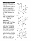
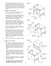
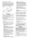
Installing The Cabinet Doors
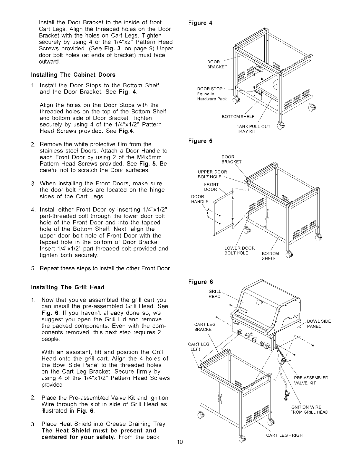
1. Install the Door Stops to the Bottom Shelf
and the Door Bracket. See Fig. 4.
Align the holes on the Door Stops with the
threaded holes on the top of the Bottom Shelf
and bottom side of Door Bracket. Tighten
securely by using 4 of the 1/4"x1/2" Pattern
Head Screws provided. See Fig.4.
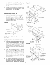
2. Remove the white protective film from the
stainless steel Doors. Attach a Door Handle to
each Front Door by using 2 of the M4x5mm
Pattern Head Screws provided. See Fig. 5. Be
careful not to scratch the Door surfaces.
3. When installing the Front Doors, make sure
the door bolt holes are located on the hinge
sides of the Cart Legs.
4. Install either Front Door by inserting 1/4"xl/2"
part-threaded bolt through the lower door bolt
hole of the Front Door and into the tapped
hole of the Bottom Shelf. Next, align the
upper door bolt hole of Front Door with the
tapped hole in the bottom of Door Bracket.
Insert 1/4"x1/2" part-threaded bolt provided and
tighten both securely.
5. Repeat these steps to install the other Front Door.
Figure 4
DOOR
BRACKET
DOOR
Found in
Hardware Pack
BOTTOMSHELF
Figure 5
DOOR
BRACKET
UPPER DOOR
BOLT HOLE
FRONT
DOOR
DOOR
HANDLE
\
LOWER DOOR
BOLT HOLE
TANK PULL-OUT
TRAY KIT
BOTTOM
SHELF
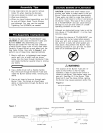
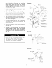
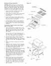
Installing The Grill Head
Now that you've assembled the grill cart you
can install the pre-assembled Grill Head. See
Fig. 6. If you haven't already done so, we
suggest you open the Grill Lid and remove
the packed components. Even with the com-
ponents removed, this next step requires 2
people.
With an assistant, lift and position the Grill
Head onto the grill cart. Align the 4 holes of
the Bowl Side Panel to the threaded holes
on the Cart Leg Bracket. Secure firmly by
using 4 of the 1/4"x1/2" Pattern Head Screws
provided.
Figure 6
GRILL
HEAD
CARTLEG
BRACKET
CART ;:;>
PRE-ASSEMBLED
VALVE KIT
2. Place the Pre-assembled Valve Kit and Ignition
Wire through the slot in side of Grill Head as
illustrated in Fig. 6.
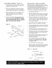
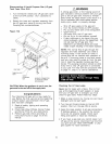
IGNITION WIRE
FROM GRILL HEAD
.
Place Heat Shield into Grease Draining Tray.
The Heat Shield must be present and
centered for your safety. From the back
10
CART LEG - RIGHT