


Special offers from our partners!

Find Replacement BBQ Parts for 20,308 Models. Repair your BBQ today.
.
.
.
7.
.
.
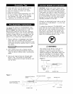
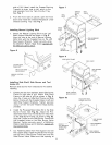
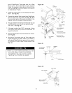
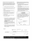
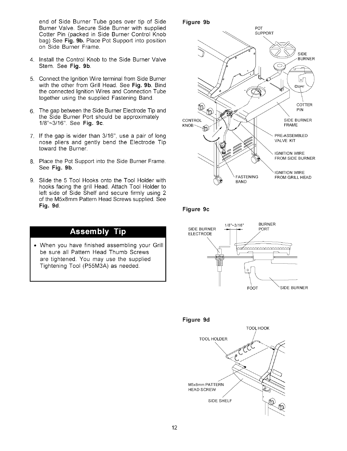
end of Side Burner Tube goes over tip of Side
Burner Valve. Secure Side Burner with supplied
Cotter Pin (packed in Side Burner Control Knob
bag) See Fig. 9b. Place Pot Support into position
on Side Burner Frame.
Install the Control Knob to the Side Burner Valve
Stem. See Fig. 9b.
Connect the Ignition Wire terminal from Side Burner
with the other from Grill Head. See Fig. 9b. Bind
the connected Ignition Wires and Connection Tube
together using the supplied Fastening Band.
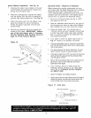
The gap between the Side Burner Electrode Tip and
the Side Burner Port should be approximately
1/8"~3/16 ''. See Fig. 9c.
If the gap is wider than 3/16", use a pair of long
nose pliers and gently bend the Electrode Tip
toward the Burner.
Place the Pot Support into the Side Burner Frame.
See Fig. 9b.
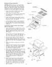
Slide the 5 Tool Hooks onto the Tool Holder with
hooks facing the grill Head. Attach Toot Holder to
left side of Side Shelf and secure firmly using 2
of the M5x8mm Pattern Head Screws supplied. See
Fig. 9d.
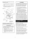
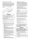
• When you have finished assembling your Grill
be sure aN Pattern Head Thumb Screws
are tightened. You may use the supplied
Tightening Tool (P55M3A) as needed.
Figure 9b
POT
SUPPORT
\
SIDE
JRNER
COTTER
PIN
BAND
PRE-ASSEMBLED
VALVE KIT
IGNITION WIRE
FROM SIDE BURNER
3NITION WIRE
FROM GRILL HEAD
Figure 9c
1/8"~3/16" BURNER
SIDE BURNER _ PORT
_URNER
Figure 9d
TOOL HOLDER
TOOLHOOK
M5x8mm PATTERN
HEAD SCREW
SIDE SHELF
12