


Special offers from our partners!

Find Replacement BBQ Parts for 20,308 Models. Repair your BBQ today.
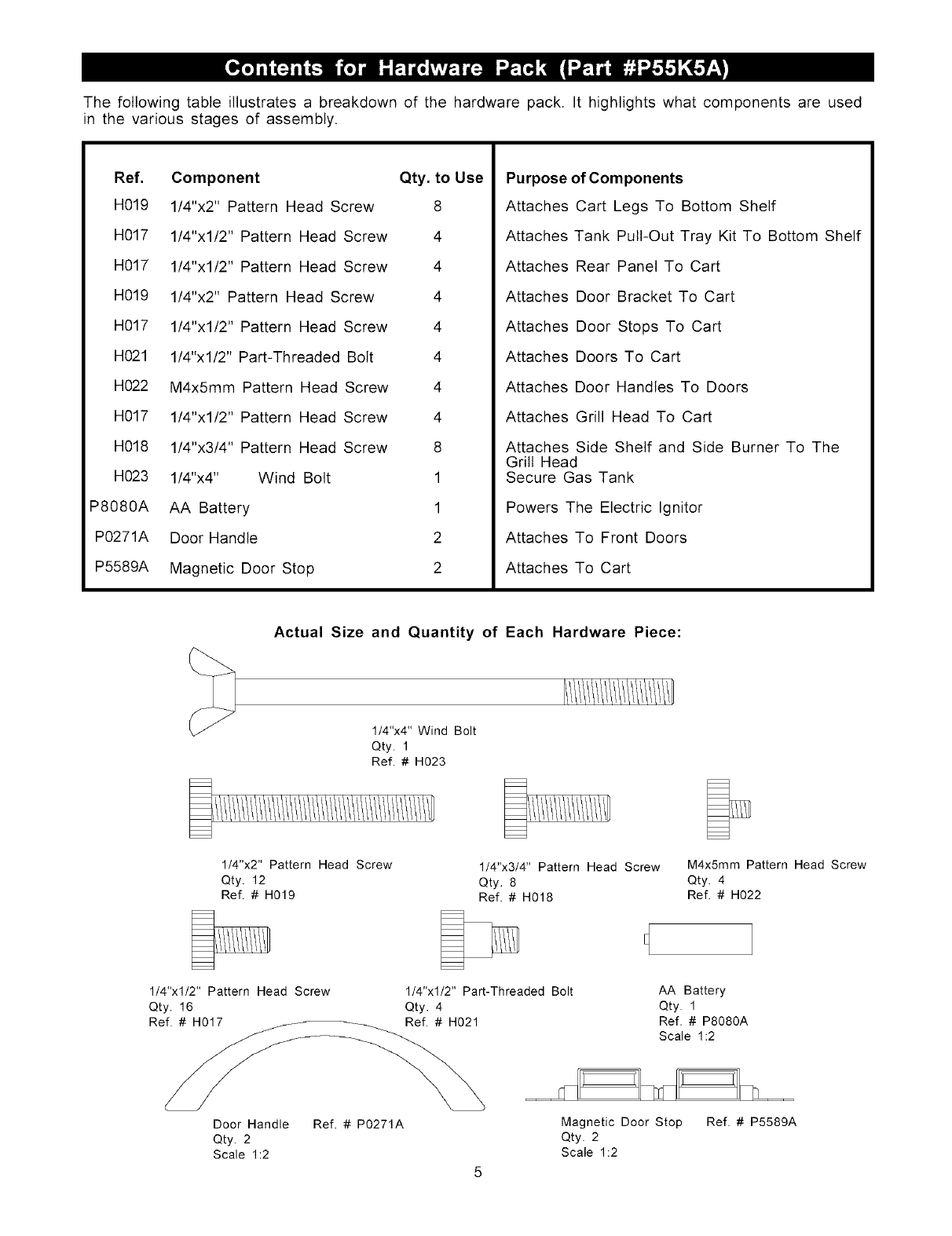
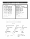
The following table illustrates a breakdown of the hardware pack. It highlights what components are used
in the various stages of assembly.
Ref.
H019
H017
H017
H019
H017
H021
H022
H017
H018
H023
P8080A
P0271A
P5589A
Component Qty. to Use
1/4"x2" Pattern Head Screw 8
1/4"xl/2" Pattern Head Screw 4
1/4"xl/2" Pattern Head Screw 4
1/4"x2" Pattern Head Screw 4
1/4"xl/2" Pattern Head Screw 4
1/4"xl/2" Part-Threaded Bolt 4
M4x5mm Pattern Head Screw 4
1/4"xl/2" Pattern Head Screw 4
1/4"x3/4" Pattern Head Screw 8
1/4"x4" Wind Bolt 1
AA Battery 1
Door Handle 2
Magnetic Door Stop 2
Purpose of Components
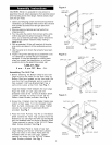
Attaches Cart Legs To Bottom Shelf
Attaches Tank Pull-Out Tray Kit To Bottom Shelf
Attaches Rear Panel To Cart
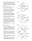
Attaches Door Bracket To Cart
Attaches Door Stops To Cart
Attaches Doors To Cart
Attaches Door Handles To Doors
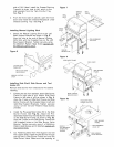
Attaches Grill Head To Cart
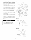
Attaches Side Shelf and Side Burner To The
Grill Head
Secure Gas Tank
Powers The Electric Ignitor
Attaches To Front Doors
Attaches To Cart
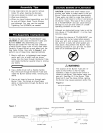
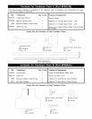
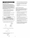
Actual Size and Quantity of Each Hardware Piece:
1/4"x4" Wind Bolt
Qty. 1
Ref. # H023
1/4"x2" Pattern Head Screw
Qty. 12
Ref. # H019
1/4"x3/4" Pattern Head Screw M4x5mm Pattern Head Screw
Qty. 8 Qty. 4
Ref. # H018 Ref. # H022
1/4"xl/2" Pattern Head Screw
Qty. 16
Ref. # H017
1/4"xl/2" Part-Threaded Bolt AA Battery
Qty. 4 Qty. 1
Ref. # H021 Ref. # P8080A
Scale 1:2
Door Handle
Qty. 2
Scale 1:2
Ref. # P0271A Magnetic Door Stop
Qty. 2
Scale 1:2
Ref. # P5589A