


Special offers from our partners!

Find Replacement BBQ Parts for 20,308 Models. Repair your BBQ today.

Outdoor Lifestyles by Hearth & Home Technologies Inc. • Carolina • 4066-300 • Rev. Q • 7/11 11
A. Fuel Conversion
Before making gas connections ensure appliance being
installed is compatible with the available gas type.
Any natural or propane gas conversions necessary to meet
the appliance and locality needs must be made by a quali-
fi ed technician using Hearth & Home Technologies speci-
fi ed and approved parts.
Pressure requirements for appliance are shown in the table
below.
Note: Have the gas supply line installed in accordance
with local building codes, if any. If not, follow ANSI
223.1. Installation should be done by a qualifi ed installer
approved and/or licensed as required by the locality. (In
the Commonwealth of Massachusetts installation must be
performed by a licensed plumber or gas fi tter.)
Note: A listed (and Commonwealth of Massachusetts
approved) 1/2 in. (13 mm) T-handle manual shutoff valve and
fl exible gas connector are connected to the 1/2 in. (13 mm)
control valve inlet.
• If substituting for these components, please consult
local codes for compliance.
B. Gas Pressure
Proper input pressures are required for optimum appliance
performance. Gas line sizing requirements need to be
made following NFPA51.
5
5
Gas Information
Fire Risk
Explosion Risk
High pressure will damage valve.
• Disconnect gas supply piping BEFORE
pressure testing gas line at test pressures
above 1/2 psig.
• Close the manual shutoff valve BEFORE
pressure testing gas line at test pressures
equal to or less than 1/2 psig.
Low pressure may cause explosion.
WARNING
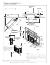
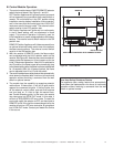
Note: Gas line MUST be run from right side of appliance.
These pressures can be verifi ed through the access panel
as shown in Section E. Valve Access.
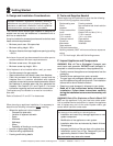
Pressure Natural Gas Propane
Minimum Inlet Pressure 5.0 inches w.c. 11.0 inches w.c.
Maximum Inlet Pressure 10.0 inches w.c. 13.0 inches w.c.
Manifold Pressure 3.5 inches w.c. 10.0 inches w.c.
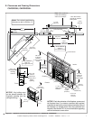
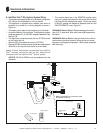
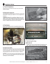
C. Gas Connection
The access panel is located below the control box. It will
be easier to make gas connection after the control box is in
its fi nal position. If necessary, relocate control box prior to
making gas connection. See Section 5.E.
• Remove the screws holding the access panel.
• Set the panel and screws aside for reinstallation.
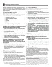
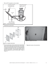
Control Box
Access Panel
Figure 5.1 Control Box & Access Panel Locations
If control box is to be relocated, move it at this time to avoid
making the gas connection more than once.
• The incoming gas line can be installed from the bottom
of the fi replace structure, from the side or from the rear
(drilling through the cement board may be necessary).
• The incoming line should be connected to the 1/2 in.
connection on the manual shutoff valve provided with the
fi replace.