


Special offers from our partners!

Find Replacement BBQ Parts for 20,308 Models. Repair your BBQ today.

5
can be fitted by anyone capable of simple DIY jobs and
requires no special training. This upgrade can be obtained
through your local Gazco stockist.
5.2 STANDARD REMOTE CONTROL This remote control can
control the fire after the pilot has been lit. It can turn the
main burner on and regulate it from low through to high and
back again. It can turn the main burner off leaving the pilot
burning GAZCO PART NUMBER 8455.
6. CLEANING THE FIRE
6.1 Remove the ceramic coals or pebbles and place on a dry,
clean surface. Remove the fuel bed and the burner cover
gasket.
6.2 Clean the burner and tray assembly using a vacuum cleaner
with soft brush attachment, ensure all debris is removed from
the burner ports.
6.3 Replace the ceramics by referring to section 7.
7. ARRANGEMENT OF FUEL BED
COMPONENTS
NOTE: CERAMIC PARTS ARE FRAGILE. THE SIDE AND
REAR PANELS ARE REVERSIBLE. ONE SIDE IS PLAIN, THE
OTHER SIDE IS REEDED. ASK THE CUSTOMER WHICH
SIDE IS PREFERRED AT THIS STAGE.
ONLY USE THE CORRECT TYPE AND QUANTITY OF
CERAMIC COMPONENTS. POINTS 7.1 TO 7.5 ARE
COMMON TO ALL FUEL TYPES AND LAYOUTS.
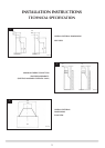
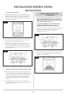
7.1 Position the burner cover gasket on the burner skin ensuring
the holes align with the ports. Take care as the front
left-hand hole is offset compared to the others.
See diagram 3, arrow A.
3
AR1175
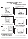
7.2 Position the flame baffle centrally on the tray and ensure the
stepped lower edge engages against the rear edge of the
burner skin. See diagram 4.
4
AR1159
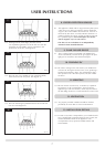
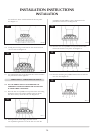
7.3 Place the rear panel against the rear of the box and slide
the side panels on either side of the flame baffle. Ensure they
locate in the brackets at the top of the firebox. DO NOT
SLIDE THEM ALL THE WAY BACK. See diagram 5.
5
AR1161
7.4 Locate the top panel on top of the rear and side panels.
Finally push the sides fully towards the rear panel. This will
retain the top panel. See diagram 6.
6
AR1162
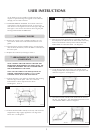
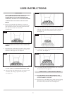
7.5 Place the front coal centrally in the channel at the front of
the tray. See diagram 7. The relationship between the front
coal and flame baffle is shown in diagram 7.
7
AR1160
AR1163
USER INSTRUCTIONS