


Special offers from our partners!

Find Replacement BBQ Parts for 20,308 Models. Repair your BBQ today.

14
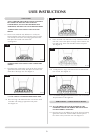
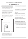
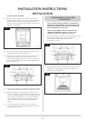
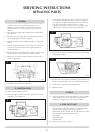
B) SCREW FIXING METHOD
6.8 Alternatively, this appliance can be secured back to the
fire place opening using the screws and rawl plugs provided.
Place the firebox centrally in the opening and mark the
positions of the 4 fixing holes. Drill the holes and insert the 4
rawl plugs. See diagram 7.
7
AR1158
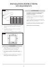
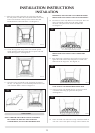
6.9 Offer the firebox into the opening and ensure that the gas
supply pipe passes through the rubber seal.
6.10 Refit the burner assembly and secure the 6 pozidriv screws.
Connect the gas supply to the inlet connection on the
burner unit and tighten. It may be necessary to support the
inlet connection with another spanner whilst tightening this
joint. See diagram 8.
8
AR1175
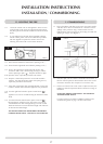
6.11 Turn on the gas supply to the appliance and check for leaks.
Light the fire and check all joints on the appliance for leaks.
6.12 Remove the sealing screw from the inlet connection and
connect a suitable “U” gauge manometer. Light the fire and
turn to the maximum position, refer to the data badge and
ensure that the running pressure is correct. If the pressure
varies significantly from that on the data badge, this may
indicate a supply problem and will require immediate
attention.
6.13 Turn the appliance off, disconnect the “U” gauge and
replace the sealing screw. Relight the appliance and check
the sealing screw for leaks.
INSTALLATION INSTRUCTIONS
INSTALLATION
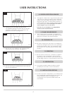
7. ARRANGEMENT OF FUEL BED
COMPONENTS
NOTE: CERAMIC PARTS ARE FRAGILE. THE SIDE AND
REAR PANELS ARE REVERSIBLE. ONE SIDE IS PLAIN, THE
OTHER SIDE IS REEDED. ASK THE CUSTOMER WHICH
SIDE IS PREFERRED AT THIS STAGE.
ONLY USE THE CORRECT TYPE AND QUANTITY OF
CERAMIC COMPONENTS. POINTS 7.1 TO 7.5 ARE
COMMON TO ALL FUEL TYPES AND LAYOUTS.
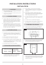
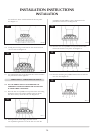
7.1 Position the burner cover gasket on the burner skin ensuring
the holes align with the ports. Take care as the front
left-hand hole is offset compared to the others.
See diagram 9, arrow A.
9
AR1175
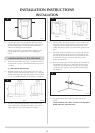
7.2 Position the flame baffle centrally on the tray and ensure the
stepped lower edge engages against the rear edge of the
burner skin. See diagram 10.
10
AR1159