


Special offers from our partners!

Find Replacement BBQ Parts for 20,308 Models. Repair your BBQ today.
Part # 4526884 Rev 4 (10/08/10)Page 10
INSTALLATION continued
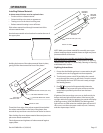
Installation of Kit:
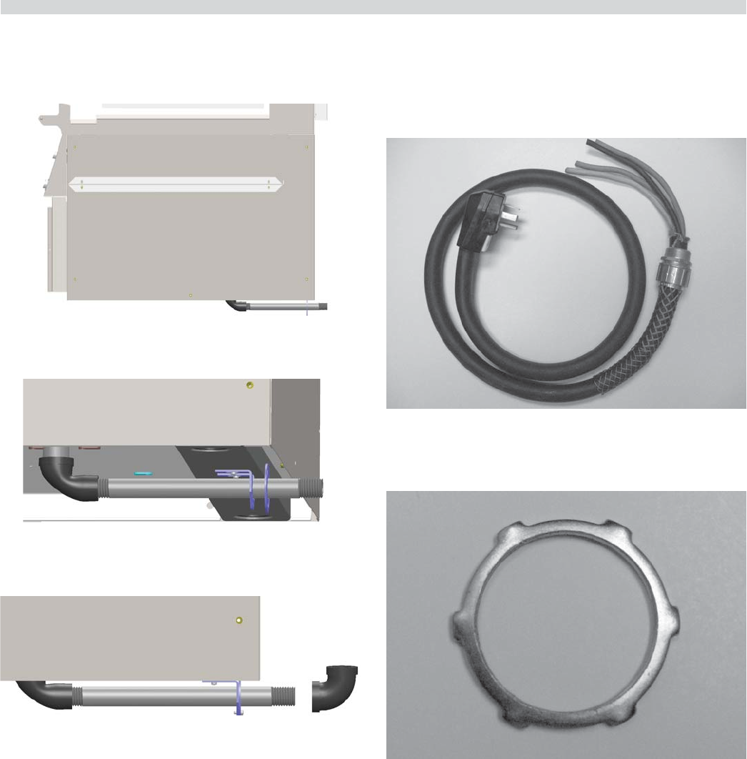
1. Install the nipple assembly in the reduction elbow
(3/4” NPT) connected to the manifold. (Figure A)
Figure A
2. Install the manifold support bracket over the nipple and
leave the two screws loose. (Figure B)
Figure B
3. Adjust the manifold support bracket ush with the rear
gas support bracket. (Figure C)
Figure C
4. Tighten the two loose screws of the manifold support
bracket onto the frame U-channel.
5. Lock the two brackets together using two screws.
(Figure C)
6. ¾” 90 degree elbow is supplied, to be installed if required.
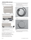
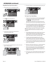
Accessory Kit – Electrical Supply Lines:
The accessory kit also contains electric power cord and
plug and has a stain relief suited for each unit. See Plug
Con guration in SPECIFICATIONS and Photo D
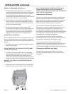
Installation of Cord And Plug With Strain Relief:
1. Remove the left grease bucket support attached by two
metal screws and the stainless steel left side body panel
attached by ve metal screws.
2. Remove the cord & plug and strain relief assembly from
the accessory kit. Refer to photo D.
Photo D
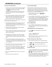
3. Remove the locknut from at the end of the cord. Refer to
photo E.
Photo E
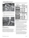
4. Insert loose wires and strain relief cord end through the
hole at the bottom of the unit Refer to photo F and secure
with locknut. Refer to photo E.