


Special offers from our partners!

Find Replacement BBQ Parts for 20,308 Models. Repair your BBQ today.
www.desatech.com
119303-01A
14
INSTALLATION
Continued
Installation must include an equipment shutoff
valve, union and plugged 1/8" NPT tap. Locate
NPT tap within reach for test gauge hook up.
NPT tap must be upstream from replace (see
Figure 18).
IMPORTANT: Install equipment shutoff valve
in an accessible location. The equipment shutoff
valve is for turning on or shutting off the gas to
the appliance.
Check your building codes for any special re-
quirements for locating equipment shutoff valve
to replaces.
Apply pipe joint sealant lightly to male NPT
threads. This will prevent excess sealant from
going into pipe. Excess sealant in pipe could result
in clogged replace valves.
We recommend that you install a sediment trap in
supply line as shown in Figure 18. Locate sediment
trap where it is within reach for cleaning. Install in
piping system between fuel supply and replace.
Locate sediment trap where trapped matter is not
likely to freeze. A sediment trap traps moisture
and contaminants. This keeps them from going
into replace gas controls. If sediment trap is not
installed or is installed wrong, replace may not
run properly.
* Purchase the optional CSA design-certified
equipment shutoff valve from your dealer. See
Accessories, page 26.
** Minimum inlet pressure for purpose of input
adjustment.
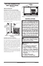
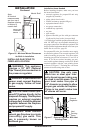
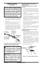
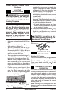
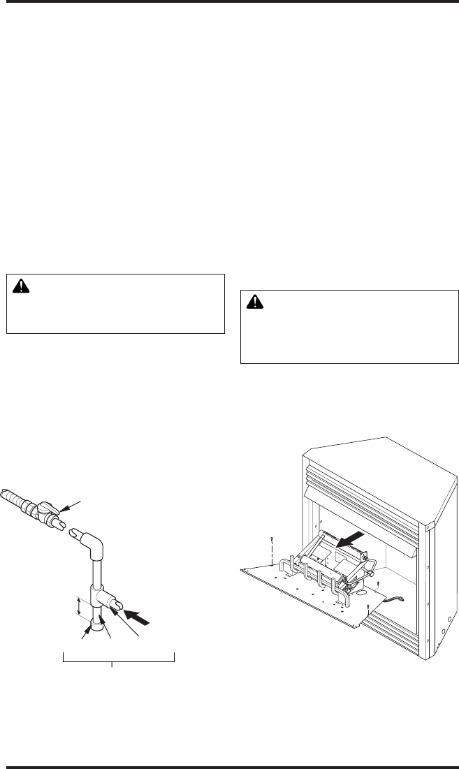
Figure 18 - Gas Connection
Sediment Trap
CSA Design-Certied
Equipment Shutoff Valve
With 1/8" NPT Tap*
3" Minimum
Cap Pipe Tee
Nipple Joint
Natural Gas
From Gas Meter
(5" W.C.** to 10.5"
W.C. Pressure)
From External
Regulator
(11" W.C.** to 14"
W.C. Pressure)
Installation Items Needed
• 5/16" hex socket wrench or nut-driver
• Phillips screwdriver
• sealant (resistant to propane/LP gas, not pro-
vided)
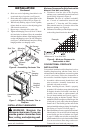
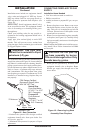
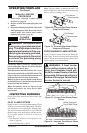
1. Remove replace screen. Remove one screw
that holds replace screen in place for ship-
ping. This screw is located near top left side
of screen. Discard screw. Lift replace screen
up and pull out to remove.
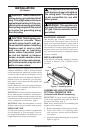
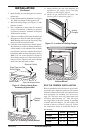
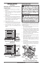
2. Remove screws that attach log base assembly
to replace (see Figure 19). Carefully lift up
log base assembly and remove from replace
(see Figure 19).
Note: If adding the G8000 series brick liner acces-
sory, install it now. Follow instructions in G8000
accessory kit.
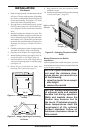
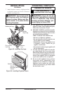
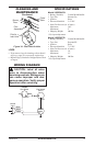
3. Route gas line (provided by installer) from
equipment shutoff valve to replace. Route
exible gas supply line through one of the
access holes.
Figure 19 - Removing Log Base
Assembly From Fireplace