


Special offers from our partners!

Find Replacement BBQ Parts for 20,308 Models. Repair your BBQ today.
www.desatech.com
119303-01A
10
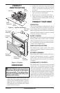
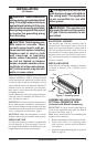
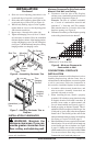
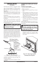
4. Slide one end of adjusting plate/shim in slot
on mitered edge of top trim (see Figure 6).
5. Slide other end of adjusting plate/shim in slot
on mitered edge of side trim (see Figure 6).
6. While rmly holding edges of trim together,
tighten both set screws on the adjusting plate
with slotted screwdriver.
7. Repeat steps 1 through 6 for other side.
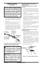
8.
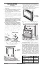
Tighten trim hanging screws (#10 x 6.25 shoul-
der) into holes in cabinets. Place the assembled
trim onto replace cabinet. Align hanging notches
on trim with hanging screws on side of replace
(see Figure 7). Push trim rmly into place, sliding
hanging notches over hanging screws.
INSTALLATION
Continued
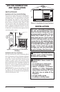
INSTALLATION CLEARANCES
WARNING: Maintain the
Carefully follow these instructions. This will
ensure safe installation.
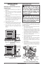
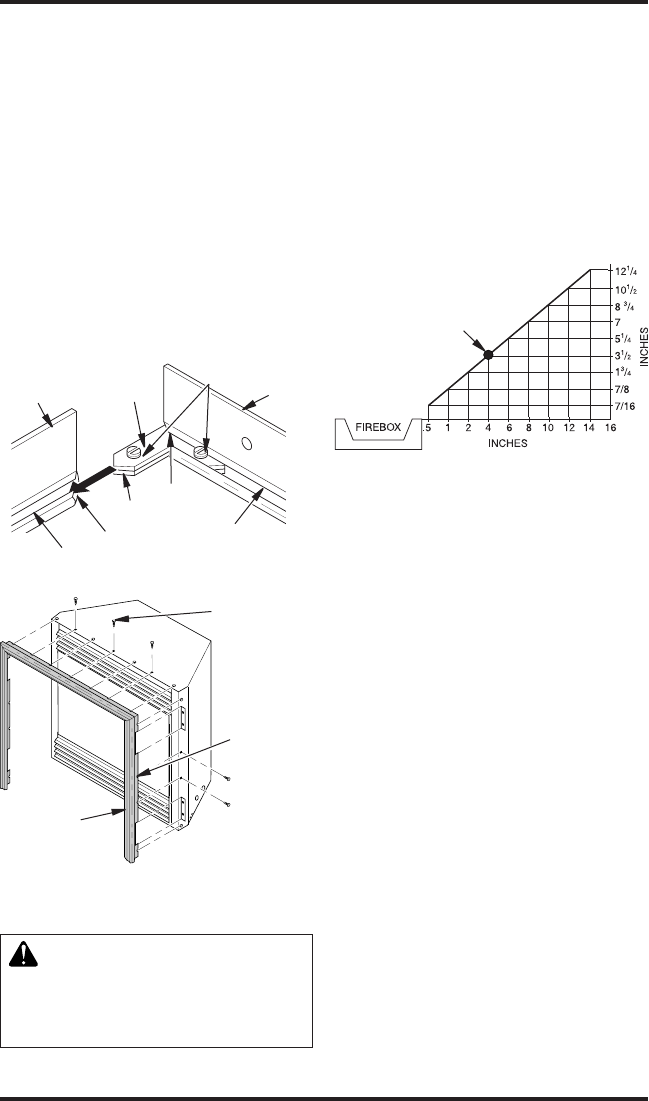
*Minimum 16" from Side Wall
*
Example
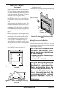
Figure 8 - Minimum Clearance for
Combustible to Wall
A. Clearances from the side of the fireplace
cabinet to any combustible material and wall
should follow diagram in Figure 8.
Example: The face of a mantel, bookshelf,
etc. is made of combustible material and
protrudes 3
1
/
2
" from the wall. This combus-
tible material must be 4" from the side of the
replace opening (see Figure 8).
B. Clearances from the top of the replace opening
to the ceiling should not be less than 42".
INSTALLATION
Conventional installation of this replace involves
installing replace along with the corner, face, or
cabinet mantel with hearth base accessories against
a wall in your home. Follow the instructions in
this section to install the replace in this manner.
1. Assemble cabinet mantel, hearth base, and
trim accessories. Assembly instructions are
included with each accessory.
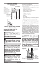
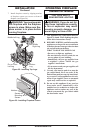
2. When installing blower, install a properly
grounded, 120 volt three-prong electrical outlet
at replace location if an outlet is not there. If
possible, locate outlet so cabinet mantel will
cover it when installed (see Figure 9, page 11).
3. Install gas piping to replace location. This in-
stallation includes an approved exible gas line
(if allowed by local codes) after the equipment
shutoff valve. The exible gas line must be the
last item installed on the gas piping. See Installing
Gas Piping to Fireplace Location, page 13.
4. Place hearth base accessory against wall at instal-
lation location. Cut an access hole in hearth top
to run exible gas line to replace (see Figure
9, page 11). Make sure to locate access hole so
cabinet mantel will cover it when installed. Note:
You can secure base to oor using wood screws.
Countersink screw heads and putty over.
Figure 6 - Assembling Perimeter Trim
Side Trim
Slot
Mitered
Edge
Slot
Shim
Set Screws
Adjusting
Plate
Top
Trim
Mitered
Edge
Assembled
Trim
Figure 7 - Attaching Perimeter Trim to
Fireplace
Trim
Hanging
Screws
Hanging
Notches
on Trim