


Special offers from our partners!

Find Replacement BBQ Parts for 20,308 Models. Repair your BBQ today.

www.desatech.com
113111-01E 11
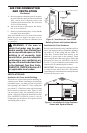
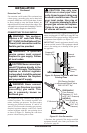
WARNING: Do not allow any
WARNING: Do not allow
WARNING: Never modify or
cover the louvered slots on the
-
-
cal outlet is included with the
-
2. If installing GA3450TA blower accessory, do
so at this time. See Installing Blower Acces-
sory GA3450TA, page 13.
Note: If not installing blower accessory, you
may wish to run electrical wiring to your
replace for future blower installation (see
Accessories, page 30) Use only approved
three-wire electrical wiring.
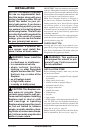
Note: A qualied installer should make all
electrical connections.
3. Install gas piping to replace location. This
installation includes an approved exible gas
line (if allowed by local codes) after the equip-
ment shutoff valve. The exible gas line must
be the last item installed on the gas piping.
4. If you have not assembled rebox, follow
instructions on page 4.
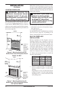
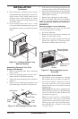
5. Carefully set replace in front of rough opening
with back of replace inside wall opening.
6. Attach exible gas line to replace gas regula-
tor. See Connecting to Gas Supply, page 16.
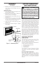
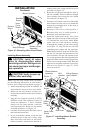
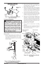
7. Bend four nailing anges on outer casing with
pliers (see Figure 10).
8. Attach fireplace to wall studs using nails
or wood screws through holes in nailing
ange.
9. Check all gas connections for leaks. See
Checking Gas Connections, page 18.
10. If using optional trim kit, install the trim after
nal nishing and/or painting of wall. See
instructions included with trim accessory for
attaching trim.
IMPORTANT: When finishing your firebox,
combustible materials
INSTALLATION
Continued
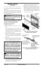
36
5
/
8
"
25
7
/
8
"
51
3
/
4
"
26
7
/
8
"
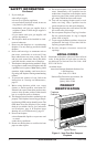
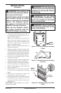
Figure 9 - Rough Opening for Installing
in Corner
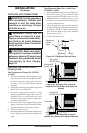
26
7
/8
"
26
7
/8
"
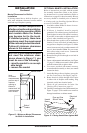
3/4" Off
The Floo
r
Minimum
10
1
/2
"
Figure 8 - Rough Opening for Installing
in Wall
Figure 10 - Attaching Fireplace to Wall
Studs
Nails or
Wood
Screws
Nailing
Flanges