


Special offers from our partners!

Find Replacement BBQ Parts for 20,308 Models. Repair your BBQ today.
www.desatech.com
116238-01D 7
A
B
E
F
G
H
D
C
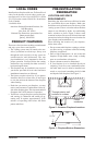
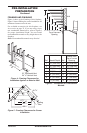
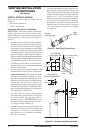
Nailing Tabs
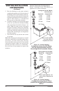
Figure 4 - Framing Clearances for
Installation Against an Exterior Wall
36
1
/8"
41
1
/4"
21" Horizontal Vent
24
1
/2" Vertical Vent
C
B
A
D
E
F
G
Top of Louver
Opening
3
2
1
4
5
6
7
Wall
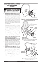
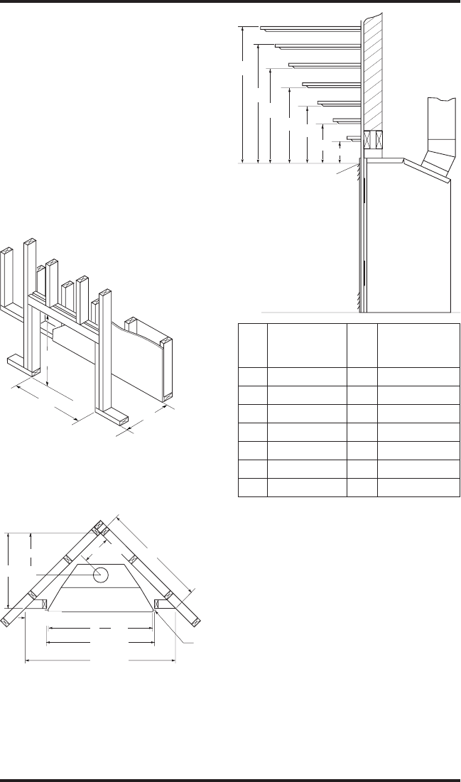
Figure 5 - Framing Clearances for Corner
Installation
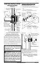
Ref. Mantel Depth Ref.
Mantel from
Top of Louver
Opening
1 14" (356 mm) A 16" (406 mm)
2 12" (305 mm) B 14" (356 mm)
3 10" (254 mm) C 12" (305 mm)
4 8" (203 mm) D 10" (254 mm)
5 6" (152 mm) E 8" (203 mm)
6 4" (101 mm) F 6" (152 mm)
7 2" (51 mm) G 4" (101 mm)
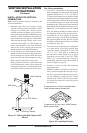
Figure 6 - Clearances for Combustible
Mantels
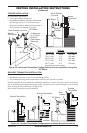
41"
41
1
/
4
"
35
3
/
4
"
15"
49
5
/8"
13
3
/
4
"
68
1
/
2
"
10
3
/
8
"
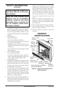
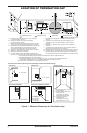
PRE-INSTALLATION
PREPARATION
Continued
Nailing
Tabs
FRAMING AND FINISHING
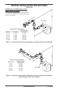
Figure 4 shows typical framing of this replace.
Figure 5 shows framing for corner installation. All
minimum clearances must be met.
For available accessories for this replace, see
Accessories on page 35. If you are using a sepa-
rate combustible mantel piece, refer to Figure 6
for proper installation height. You can install
noncombustible mantels at any height above the
replace.
Note: Noncombustible mantels may discolor!