


Special offers from our partners!

Find Replacement BBQ Parts for 20,308 Models. Repair your BBQ today.

www.desatech.com
116238-01D 29
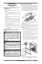
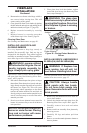
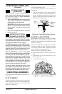
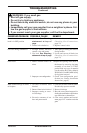
Figure 45 - Typical Flame Pattern
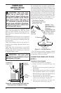
OPTIONAL REMOTE
OPERATION
Note: The WRC receiver and hand-held re-
mote control kit must be purchased separately
(see Accessories, page 35). Follow installation
instructions on page 26.
1. Turn equipment shutoff valve to ON position.
You can now turn the burner on and off with
the hand-held remote control unit.
IMPORTANT: Be sure to press the ON/OFF
buttons on the hand-held remote control
unit for up to 3 seconds to assure proper
operation.
2. Press the ON/OFF button to turn the
burner on and off.
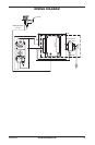
OPERATING OPTIONAL
Locate the blower controls by opening the lower
louver panel on the replace. Blower controls
are located on the left side of the switch bracket
to the right just inside the louver panel.
The BK manual blower and the BKT thermo-
statically-controlled blower have an ON setting
and an OFF setting. The blower will only run
when the switch is in the ON position. In the
OFF position, the blower will not operate.
If you are using BKT
blower with optional thermostat (wall mounted
or remote control) for the replace, your re-
place and blower will not turn on and off at the
same time. The replace may run for several
minutes before the blower turns on. After the
heater modulates to the pilot position, the blow-
er will continue to run. The blower will shut off
after the rebox temperature decreases.
The blower helps distribute heated air from
the replace. Periodically check the louvers of
the rebox and remove any dust, dirt or other
obstructions that will hinder the ow of air.
OPERATING FIREPLACE
Continued
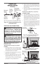
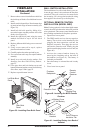
INSPECTING BURNERS
Check pilot ame pattern and burner ame pat-
terns often.
The pilot assembly is factory preset for the proper
ame. Alterations may have occurred during ship-
ping and handling. The pilot is located on the left
hand side of the burner.
The ame must envelope 1/4" of top of the ignitor/
sensor and grounding stem.
If your pilot assembly does not meet these re-
quirements:
• Turn the adjustment screw marked PILOT
clockwise to decrease or counterclockwise to
increase the ame to proper size (see Figure 42,
page 28). Do not remove the adjustment screw.
• see Troubleshooting, page 31
Pilot
Burner
Ignitor/
Sensor
Figure 44 - Correct Pilot Flame Pattern
Sensing
Rod
Burner ames will be steady; not lifting or oating.
Flame patterns will be different from unit to unit
and will vary depending on installation type and
weather conditions.
If the vent conguration is installed incorrectly,
the ames will lift or "ghost". This can be danger-
ous. Inspect the ames after installation to ensure
proper installation and performance.
Figure 45 shows a typical ame pattern.
If burner flame pattern differs from that de-
scribed:
• turn replace off (see To Turn Off Gas to Ap-
pliance, page 28)
• see Troubleshooting, page 31