


Special offers from our partners!

Find Replacement BBQ Parts for 20,308 Models. Repair your BBQ today.
www.desatech.com
116238-01D 31
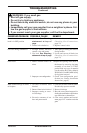
Conduct annual inspection of the venting system
following these guidelines:
1. Check areas of venting system that are ex-
posed to the weather for corrosion (rust spots
or streaks and, in extreme cases, holes). Have
these items replaced immediately by a quali-
ed service person.
CLEANING AND
MAINTENANCE
Continued
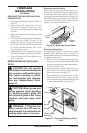
2. Remove the vent cap and shine a ashlight
into the vent. Remove any foreign material.
3. Check for evidence of excessive condensation.
Continuous condensation can cause corrosion
of caps, pipes and ttings and can be caused
by having excessive lateral runs, too many
elbows or exterior portions of the system being
exposed to cold weather.
4.
Inspect joints to verify that no pipe section or tting
has been disturbed and loosened. Check mechani-
cal supports such as wall straps for rigidity.
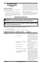
TROUBLESHOOTING
Note: Before troubleshooting the system, make sure the gas shutoff valve is ON.
The two most common causes of a malfunctioning gas appliance are:
1. Loose wiring connections
2. Construction debris clogging the pilot and/or gas control valve lter
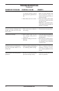
1. No gas supply or shutoff
valve is OFF
2. Air in gas line
3. Construction debris clogging
pilot orice
4. Low gas pressure
5. Kinked pilot line
6. Control valve is not opening
7. No power to unit or the igni-
tion module or power trans-
former is bad
REMEDY
1. Check to see if you have gas
supply and that equipment
shutoff valve is opened
2. Repeat lighting procedure
several times to purge all air
out of lines. If after repeated
attempts appliance does not
light, call for qualied service
and repair.
3. Remove debris and dirt, in-
spect and clean any other
possible obstructions
4. Contact your gas supplier to
check pressure
5. Have a qualified technician
replace pilot line
6. Replace control valve (Refer to
Replacement Parts, page 34)
7. Check that main power is
on and that all wire connec-
tions are made correctly to
the ignition model (see Wiring
Diagram, page 27). Check for
24 VAC at the secondary side
of the transformer. If 24 VAC
is present and the module does
not operate, have the module
replaced otherwise have the
transformer replaced
Ignitor will not spark or pilot
will not light