


Special offers from our partners!

Find Replacement BBQ Parts for 20,308 Models. Repair your BBQ today.
www.desatech.com
116238-01D24
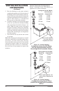
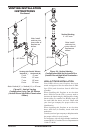
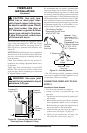
1. Open equipment shutoff valve (see Figure 33,
page 23).
2. Open propane/LP supply tank valve for
propane/LP fireplace or main gas valve
located on or near gas meter for natural gas
replace.
3. Make sure control knob of replace is in the
OFF position.
4. Check all joints from equipment shutoff valve
to gas valve (see Figure 34, page 23, for
propane/LP or Figure 35, page 23, for natural
gas). Apply noncorrosive leak detection uid
to all joints. Bubbles forming show a leak.
Correct all leaks at once.
5. Light replace (see Operating Fireplace, page
28). Check all other internal joints for leaks.
6. Turn off replace (see To Turn Off Gas to Ap-
pliance, page 28).
FIREPLACE
INSTALLATION
Continued
DOOR
-
tion see Replacement Parts,
-
-
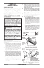
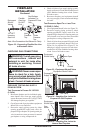
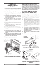
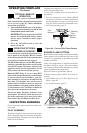
Remove the top and bottom louver panels by si-
multaneously pulling both top end spring latches
towards the center of the appliance until they are
disengaged from the locating holes (see Figure 36).
Repeat for bottom spring latches and pull the lou-
vers outward. To install or replace items removed,
simply reverse the procedures above.
Figure 36 - Removing Louver Panel
Louver
Panel
Spring
Latch
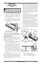
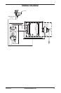
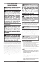
If replacement of glass is necessary, the entire
assembly, glass and frame, must be replaced. If
glass is broken, wear gloves and tape the remaining
fragments onto the frame.
1. Remove screen assembly by pushing the rod
either left or right and then down and forward
to remove screen/rod assembly from the re-
box. Set assembly aside.
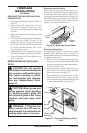
2. Lift up on latches to unlock. There are two on
top of rebox and two below rebox that hold
glass door in place (see Figure 37).
3. While holding glass door to prevent it from
falling and causing injury, remove the ve
screws from the hinge located on the left side
of door frame assembly (see Figure 37).
Lock
Unlock
Glass Frame
Assembly
Screw
Figure 37 - Removing/Replacing Glass
Door
Hinge
Latch