


Special offers from our partners!

Find Replacement BBQ Parts for 20,308 Models. Repair your BBQ today.

www.desatech.com
116238-01D26
7. Remove three screws from deector shield on
the inside top of rebox. Set shield and screws
aside.
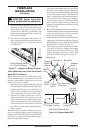
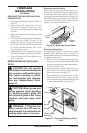
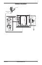
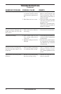
8. Install rear brick panel rst. Rest bottom edge
of panel on back edge of burner assembly (see
Figure 39).
9. Install left side brick panel by sliding it be-
tween the burner assembly and the side of the
rebox (see Figure 39).
10. Install the right brick panel using the same
method described in step 6 for left brick
panel.
11. Replace deector shield using screws removed
in step 7.
12. Using screws removed in step 6, replace
plenum and attach to burner.
13. Carefully replace the ember pod and log set.
14. Use screws removed in step 4 to replace andiron
assembly.
15. Install lava rock and glowing embers. See
Installing Lava Rock and Glowing Embers,
page 25.
16. Close glass door and lock latches on top and
bottom of door and replace screen. See Removing
Glass Door, steps 5 and 6, page 25.
17. Replace top and bottom louvers.
FIREPLACE
INSTALLATION
Continued
Figure 39 - Installing Rear Brick Panel
Rear Brick
Panel
Left Side Brick
Panel
The installation of a wall switch allows you to ac-
tivate the gas control valve and turn the replace
on and off. The wall switch is to be connected to
the incoming 120 volt regular household wiring
that supplies the electricity to the replace.
Note: If using optional wireless hand-held remote
control, the wall switch must be in the ON position
to be operational. The remote control then becomes
the switching mechanism for replace operation.
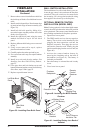
1. Open lower louver panel.
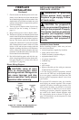
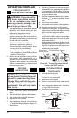
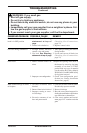
2. The WRC model receiver does not require a
battery. The receiver can be installed by rst
plugging the short extension cord into the
replace receptacle. Then plug the receiver
unit into the extension cord. Finally plug the
ignition module plug into the receiver unit (see
Figure 40).
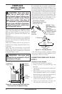
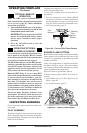
3. Activate the remote handset battery by
removing the insulating tab on the back of
the handset (see Figure 41). The battery is
included pre-installed.
4. Once the battery is activated the unit is ready
to use.
5. Close lower louver panel.
Figure 40 - Installing the WRC Remote
Receiver
Fireplace
Receptacle
Remote
Control
Receiver
Extension Cord
Ignition
Module Plug
Figure 41 - Installing Battery into Back of
Handset
Pull to Remove
Insulation Tab
Battery Cover
12 Volt Battery
Back of
Handset