


Special offers from our partners!

Find Replacement BBQ Parts for 20,308 Models. Repair your BBQ today.
8
107570
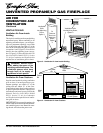
UNVENTED PROPANE/LP GAS FIREPLACE
For more information, visit www.desatech.com
INSTALLATION
Continued
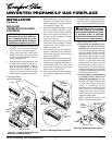
RELOCATING WALL SWITCH
Note:
The decorative wall switch plate sup-
plied is white. The wall switch plate may be
painted to match your decor.
The push-button switch and decorative wall
plate assembly supplied with your fireplace
is pre-mounted at the factory in the lower
cavity of the fireplace. You may relocate this
switch/plate assembly to a more convenient
location such as the side of your mantel or
directly onto the wall near the fireplace. To
mount the wall switch/plate assembly, you
must first cut openings in the mantel or wall
where the switch will be located.
Note:
If you choose to relocate the wall
switch, do so before final installation into a
mantel or recessing into a wall. If you are
installing an optional blower accessory, in-
stall it at the same time you relocate the wall
switch.
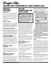
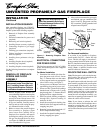
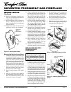
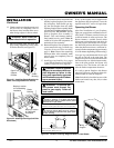
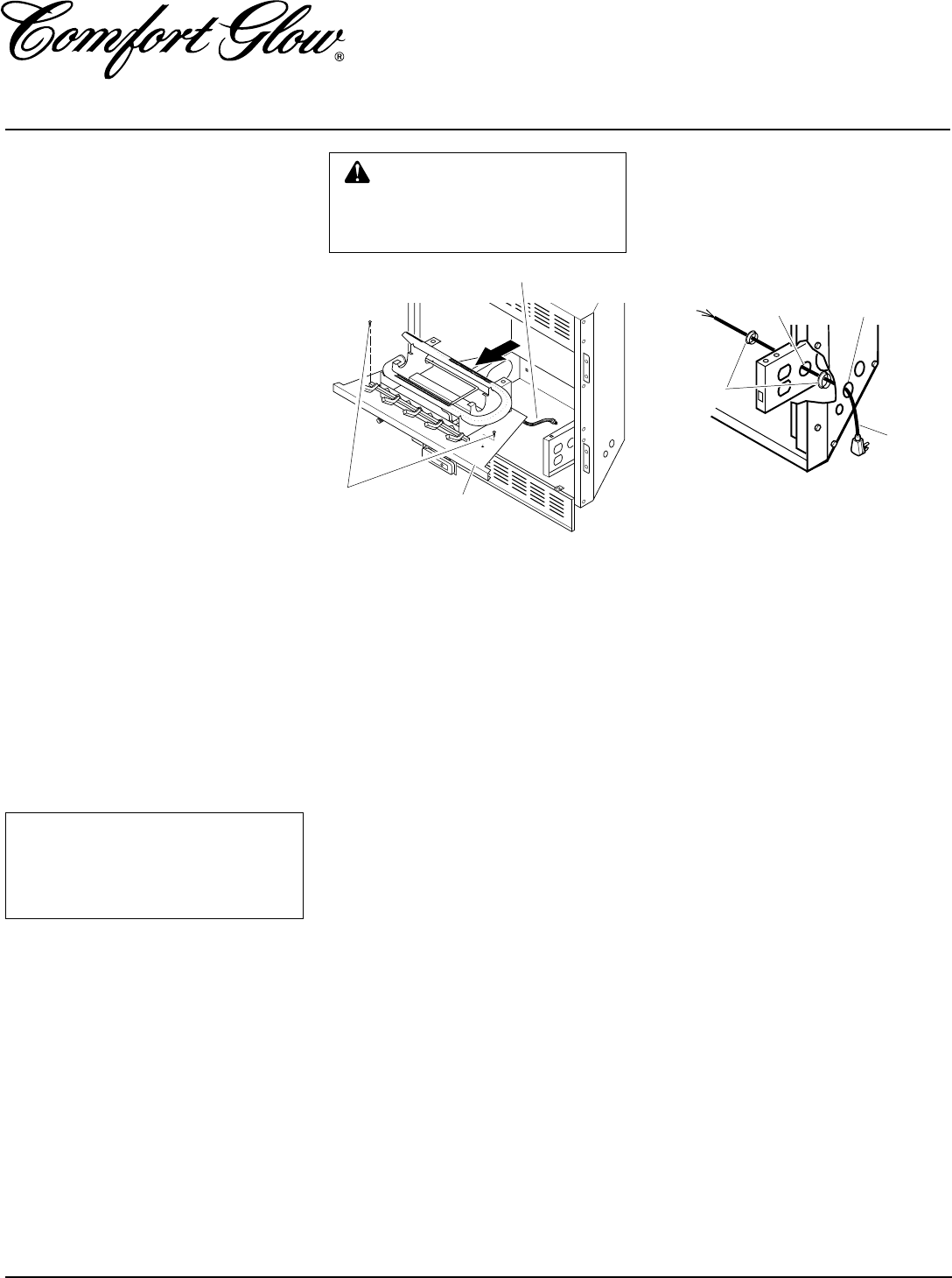
Figure 7 - Routing Power Cord
INSTALLATION SEQUENCE
After unpacking fireplace (see UNPACK-
ING, page 3), we suggest that you install your
fireplace system in the following sequence:
1. Removal of fireplace floor assembly
(required)
2. Electrical connections for power cord
(required)
3. Relocating wall switch (optional)
4. Installing blower accessory (optional)
5. Connecting fireplace to gas supply
(required)
6. Checking gas connections (required)
7. Firebox installation, conventional or
built-in (required)
8. Installing brass perimeter trim (op-
tional)
9. Installing fireplace hood (required)
10. Installing logs (required)
11. Installing fireplace screen (required)
Use the following instructions to complete
each step.
ELECTRICAL CONNECTIONS
FOR POWER CORD
This fireplace operates on 120 VAC, 60 Hz
power. An electrical power cord is supplied
with this unit.
For Mantel Installation
1. Determine from which side of the fire-
place the power cord will exit. Locate
the 1.5" diameter hole near the center
of floor support bracket on appropriate
side of lower cavity (see Figure 7).
2. Locate power cord. Remove wire tie or
tape holding plug end of power cord.
3. Power cord has 2 plastic hole bushings
threaded onto it. Route cord's 3-prong
plug through the 1.5" diameter hole in
appropriate floor support bracket.
4. Push first plastic bushing completely
through hole. Squeeze bushing as
needed to do this.
5. Install the second plastic bushing into
the hole in the floor support bracket by
snapping into place.
6. Route the 3-prong plug through the 1.5"
hole in fireplace outer casing.
7. Install the first plastic bushing into this
hole by snapping into place.
8. After you have connected to gas supply
and checked your gas connections (see
pages 14 and 15), plug power cord into
any convenient 3-prong grounded wall
receptacle near fireplace.
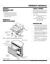
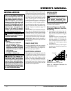
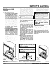
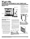
Figure 6 - Removing Fireplace Floor
Assemlby
Screws
Fireplace Floor
Assembly
Flexible Gas Line
NOTICE: Shut-off gas supply and
disconnect heater from gas sup-
ply if installing blower into previ-
ously installed fireplace. Contact a
qualified service person to do this.
CAUTION: Do not pick up fire-
place floor assembly by burners.
This could damage burners. Only
handle base by grates.
1. Remove fireplace screen. Remove two
screws that hold fireplace screen in place
for shipping. These screws are located
near top of screen. Discard screws. Lift
fireplace screen up and pull out to remove.
2. If logs are installed, carefully remove
the logs and set aside, noting the prop-
erly mounted location of each.
3. Remove screws that attach fireplace
floor assembly to fireplace. Open
lower louver door. Carefully lift up
fireplace floor assembly and remove
from fireplace, taking care to pull flex-
ible gas line through the access holes
(see Figure 6).
Note:
Be careful of all
wires on underside of log base.
REMOVAL OF FIREPLACE
SCREEN AND FLOOR
ASSEMBLY
For Recessed Installation
If an outlet is not installed in fireplace,
install model GA3555 - Outlet Kit with
Cover. This kit will supply a convenient 3-
prong grounded electrical outlet for power.
Refer to installation manual provided with
this optional accessory for instructions on
wiring.
Note:
A qualified installer must
make all electrical connections.
Power
Cord
Bushings
Hole in Floor
Support Bracket
Hole in Outer
Casing