


Special offers from our partners!

Find Replacement BBQ Parts for 20,308 Models. Repair your BBQ today.
12
107570
UNVENTED PROPANE/LP GAS FIREPLACE
For more information, visit www.desatech.com
12. Plug in blower power cord.
a. If your firebox is installed as a free-
standing unit with an accessory
mantel, determine whether the power
cord will exit the left side or the right
side of the firebox. Install one plastic
bushing provided into the 1
1
/2" hole
in the floor support on the exit side.
Install the second bushing provided
into the 1
1
/2" hole in the outer casing
through which the power cord will
exit (see Figures 21 and 22, page 13).
Route power cord through plastic
bushings and plug the power cord into
a properly grounded three-prong wall
receptacle near the firebox.
b.If your fireplace system installation
is recessed and if an outlet is not
installed in your fireplace, you must
install the GA3555 Outlet kit with
cover in your fireplace which will
supply a convenient 3-prong
grounded electrical outlet for your
blower. Refer to the installation
manual provided with the model
GA3555 accessory for instructions on
wiring the duplex outlet.
Note:
A qualified installer must
make all electrical connections.
WARNING: Failure to connect
all wires properly as indicated
may cause electrical short circuit
or personal injury. A qualified
electrician should check that all
connections are made properly.
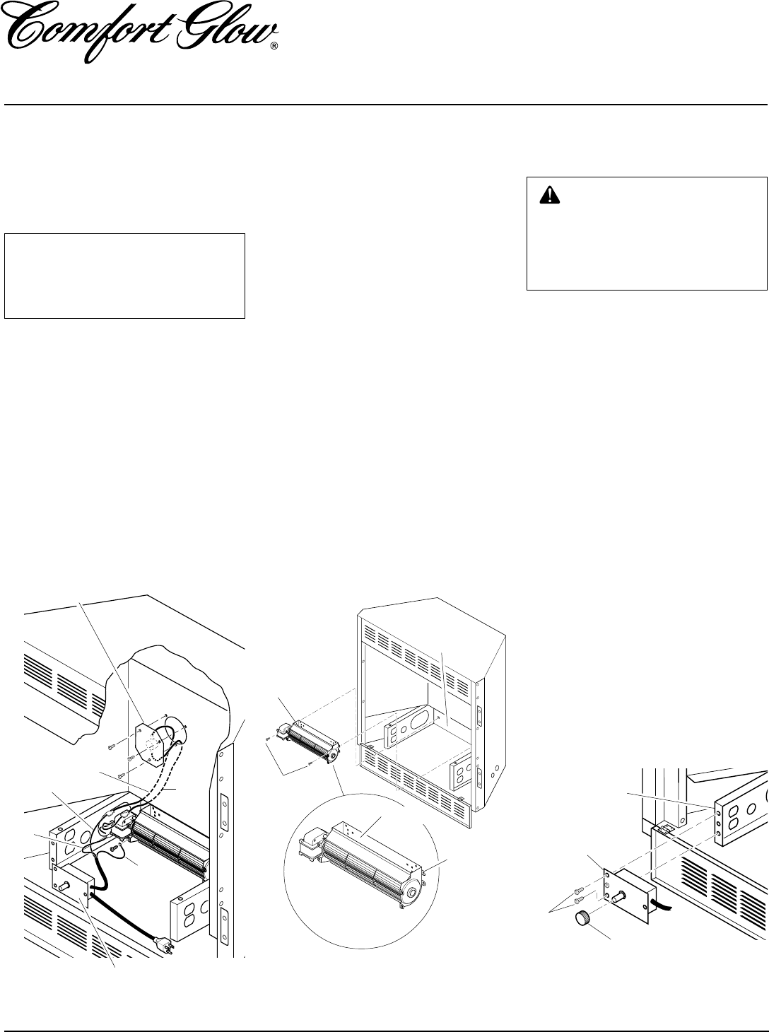
1. If fireplace screen and floor are still
installed, see Removing Fireplace
Screen and Floor Assembly, page 8.
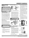
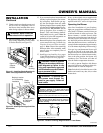
2. Using screw provided, attach green
ground wire from speed control cord
to blower housing.Tighten screw se-
curely (see Figure 18).
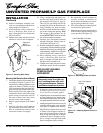
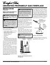
3. Place the blower against lower rear wall
of firebox outer wrapper with the ex-
haust port directed upward. Align the
holes in top mounting tabs of blower
with holes in wall of wrapper (see Fig-
ure 19). Using two #8 screws provided,
mount blower and tighten screws firmly.
4. Remove the three screws (do not dis-
card) and cover plate from center of
firebox wrapper rear wall. Discard this
cover plate (see Figure 18).
5. Mount the supplied thermostatic switch
and cover assembly into firebox wrap-
per wall. Do this by feeding terminal
ends of wire harness into the hole. Al-
low wires to fall to bottom of firebox
cavity (see Figure 18).
6. Using three screws from step 7, attach
switch and cover assembly to firebox
wrapper rear wall. Tighten screws
firmly (see Figure 18).
7. Firmly attach red wire from the ther-
mostatic switch and cover assembly to
either of the terminals on the blower
motor (see Figure 18).
8. Firmly attach black wire from speed con-
trol cord to blue wire from thermostatic
switch and cover assembly (see Figure 18).
9. Firmly attach white wire from speed
control cord to remaining terminal on
blower motor (see Figure 18).
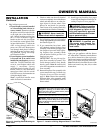
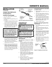
10. Place control knob provided on plastic
control shaft of speed control (see Fig-
ure 20).
NOTICE: Shut-off gas supply and
disconnect heater from gas sup-
ply if installing blower in previ-
ously installed fireplace. Contact a
qualified service person to do this.
INSTALLING
THERMOSTATIC BLOWER
ACCESSORY
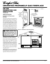
Figure 18 - Installing Switch and Cover
Assembly, and Speed Control
Thermostatic Switch
and Cover Assembly
Red
Wire
Blue
Wire
Black
Wire
Green
Wire
White
Wire
Speed Control
Figure 19 - Mounting Blower to Firebox
Blower
#8 Screws
Lower
Rear Wall
of Firebox
Exhaust
Port
Top
Mounting
Tab
Control Knob
Screws
Speed
Control
Floor
Support
Bracket
Figure 20 - Attaching Speed Control
INSTALLATION
Continued
11. Mount the speed control onto the front
leg of the left floor support bracket us-
ing 2 screws provided (see Figure 20).